
 Facebook
 Google
 GitHub
 Linkedin
Basic Electricity
Series DC Circuits Practice Worksheet with Answers
27 questions By Tony R. Kuphaldt
-
Question 7 of 27
Most flashlights use multiple 1.5 volt batteries to power a light bulb with a voltage rating of several volts. Draw a schematic diagram of showing how multiple batteries may be connected to achieve a total voltage greater than any one of the batteries’ individual voltages.
Reveal answer
Follow-up question: if each of these batteries outputs a voltage of 1.5 volts, how much voltage does the light bulb experience?
Notes:Ask the students where they would place a switch to control the light bulb in the circuit shown in the answer.
-
Question 8 of 27
A technician wants to energize a 24 volt motor, but lacks a 24 volt battery to do it with. Instead, she has access to several “power supply” units which convert 120 volt AC power from a power receptacle into low-voltage DC power that is adjustable over a range of 0 to 15 volts. Each of these power supplies is a box with a power cord, voltage adjustment knob, and two output terminals for connection with the DC voltage it produces:
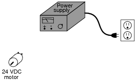
Draw a picture of how this technician might use power supplies to energize the 24 volt motor.
Reveal answerThis is perhaps the most direct solution (setting each power supply to output 12 volts):

Notes:Although this is a very simple and direct solution, it is not the only possible one. Incidentally, this scenario is very common in electronics work: having to couple multiple power supplies together to achieve a desired total voltage or total current.
-
Question 9 of 27
How much voltage does the light bulb receive in this circuit? Explain your answer.

Also, identify the polarity of the voltage across the light bulb (mark with “ ” and “-” signs).
Reveal answer
Follow-up question: draw the direction of current in this circuit.
Notes:This is a very fundamental concept that students must learn: how to determine the total voltage in a series circuit where opposing voltage sources exist. One thing mistake students sometimes make is to try to discern polarity by looking at the polarity signs at the end terminals of the end battery; i.e. at the 3-volt battery’s left-hand terminal, and the 4.5-volt battery’s right-hand terminal, then try to transfer those signs down to the load terminals. This is not an accurate way to tell polarity, but it seems to “work” for them in some situations. This problem is one example of a situation where this faulty technique most definitely does not work!
Have your students collectively agree on a procedure they may use to accurate discern series voltage sums and polarities. Guide their discussion, helping them identify principles that are true and valid for all series circuits.








llaboutcircuits.com/worksheets/series-dc-circuits/. In question 5, total series resistance is sum of each resistor, not product. Correct both question and answer
Hello Everybody and thanks for your fantastic articles!
I’m having troubles solving Excercise 19 of your Series circuits problems (https://www.allaboutcircuits.com/worksheets/series-dc-circuits/): For this excercise I’m getting a power dissipation for the heater of 403 W instead of 321.1 W.
Since I’m learning electronics I’m surely doing something wrong… Here how I’m reasoning:
1. With 110 V and a power dissipated of 500 W, I can calculate the current in the circuit, that should be I=P/V 500/110 = 4.545 A
2. Knowing that the current in the circuit is 4.545 A I can use Ohm’s law to calculate the resistance of the heater: R=V/I 110/4.545 = 24 Ohm
3. Now, longing the wires it’s the same as adding 6 Ohm of resistance, for a total resistance of 30 Ohm (24 + 6) so the current in the circuit will change accordingly. To find the new amount of current I use Ohm’s law once again: I=V/R 110/30 = 3.666 A
4. Having a new current value of 3.666 A, I can now calculate power dissipation P=V*I 110*3.666 = 403 W
Could you please help me understand where I’m wrong?
Thank you so much!
Stefano.