Facebook
 Google
 GitHub
 Linkedin
Passives
Wire-by-Number project kit introduction
3 questions By Tony R. Kuphaldt
-
Question 1 of 3
Wire-by-Number project: simple voltage divider Description:
Build a voltage divider using four resistors, powered by a 6 volt battery or power supply.
Schematic diagram:
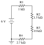
Components:
- •
- Battery (6 V): A1= , A10=- (ground)
- •
- Resistor R1, 1 kΩ: A2, A3
- •
- Resistor R2, 1.5 kΩ: A4, A5
- •
- Resistor R3, 10 kΩ: A6, A7
- •
- Resistor R4, 2.7 kΩ: A8, A9
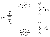
Pictorial diagram:
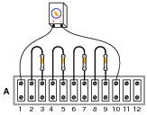
Wiring sequence:
- •
- A1-A2
- •
- A3-A4
- •
- A5-A6
- •
- A7-A8
- •
- A9-A10
Tasks:
Calculate the total resistance of this series circuit using the formula provided. Then, with the voltage source disconnected (detach the ” ” wire from terminal A1), measure the total series resistance of the four resistors, between terminals A2 and A9. Note both the predicted and the measured values in the following table, and don’t forget to include the proper unit symbol (Ω) with your data! Calculate the percentage error between the calculated (“predicted”) and measured values using the following formula: Error = [(Measured − Predicted)/Predicted] ×100 %.
Variable Formula Predicted Measured Error
Rtotal R1 R2 R3 R4
Connect the voltage source back to the circuit (attach ” ” to A1 and “-” to A10). Verify that 6 volts DC is present between terminals A1 and A10 using your voltmeter. Predict the correct values for the following voltage drops, then verify these voltage drop predictions by measuring with your voltmeter. Don’t forget to include the proper unit symbol (V) with your data!
Variable Formula Predicted Measured Error
VR1 Vsource(( R1)/(Rtotal))
VR2 Vsource(( R2)/(Rtotal))
VR3 Vsource(( R3)/(Rtotal))
VR4 Vsource(( R4)/(Rtotal))
Predict and measure current in this voltage divider circuit by breaking it open at any point and connecting a DC ammeter in series with the break. Be very careful that you do not connect your ammeter test probes directly across a source of substantial voltage, such as the battery or power supply! Remember to check your multimeter’s setting (voltage versus current) before connecting the test probes to the circuit.
Variable Formula Predicted Measured Error
Itotal [(Vsource)/(Rtotal)]
Simulate an öpen” fault in the circuit by removing resistor R3 from its terminal strip. Predict what effects this will have on the same variables (increase, decrease, or no change), then verify using your multimeter. To measure the voltage drop across R3, which is no longer in the circuit, simply measure voltage across the terminals it used to be connected to (A6 and A7):Fault condition: resistor R3 open
Variable Predicted effect Measured effect
VR1
VR2
VR3
VR4
Itotal
Explain why the variables changed as they did, and whether or not this agreed with your original expectations:
Now, simulate a ßhort” fault by connecting a piece of wire between the terminals where resistor R3 used to connect (A6 and A7), and repeat the same predictions/measurements:
Fault condition: resistor R3 shorted
Variable Predicted effect Measured effect
VR1
VR2
VR3
VR4
Itotal
Explain why the voltages changed as they did, and whether or not this agreed with your original expectations:
Questions remaining:
Here is where you write any questions or comments you have about this experiment.
-
Question 2 of 3
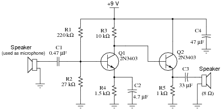
Wire-by-Number project: Two-stage, class A, audio transistor amplifier Description:
This circuit amplifies sounds detected by the microphone (actually, a small speaker used as a microphone), and amplifies them to be heard on a speaker.
Schematic diagram:
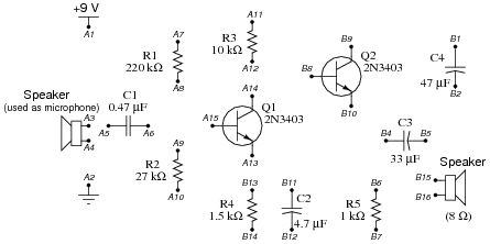
Components:
- •
- Battery (9 V): A1= , A2=- (ground)
- •
- Small speaker (used as microphone): A3, A4
- •
- Capacitor C1, 0.47 μF: A5, A6
- •
- Resistor R1, 220 kΩ: A7, A8
- •
- Resistor R2, 27 kΩ: A9, A10
- •
- Resistor R3, 10 kΩ: A11, A12
- •
- Transistor Q1, 2N3403 (NPN): A13=e, A14=c, A15=b
- •
- Capacitor C4, 47 μF: B1= , B2=-
- •
- Capacitor C3, 33 μF: B4= , B5=-
- •
- Resistor R5, 1 kΩ: B6, B7
- •
- Transistor Q2, 2N3403 (NPN): B8=b, B9=c, B10=e
- •
- Capacitor C2, 4.7 μF: B11= , B12=-
- •
- Resistor R4, 1.5 kΩ: B13, B14
- •
- Small speaker: B15, B16
Pictorial diagram:
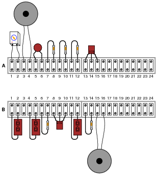
Wiring sequence:
- •
- B1-A1-A7-A11-B9
- •
- B2-A2-A4-A10-B7-B12-B14-B16
- •
- A3-A5
- •
- A6-A8-A9-A15
- •
- A12-A14-B8
- •
- A13-B13-B11
- •
- B4-B6-B10
- •
- B5-B15
Tasks:
When you have the circuit built, you should be able to lightly touch the cone of the microphone with your fingertip and hear ßcratching” sounds coming from the output speaker. If you hear no sound from the output speaker at all, even when tapping the microphone cone with your finger, then your circuit has a problem.
Predict the correct values for the following DC (quiescent) voltages, then verify by measuring with your voltmeter. Don’t forget to include the proper unit symbol (V) with your data! Calculate the percentage error of the measured values using the following formula: Error = [(Measured − Predicted)/Predicted] ×100 %
Variable Formula Predicted Measured Error
VR2 ≈ Vbattery([(R2)/(R1 R2)])
VR4 ≈ VR2 − 0.7
Vb(Q2) Vbattery − R3 ([(VR4)/(R4)])
VR5 ≈ Vb(Q2) − 0.7
Remove the bypass capacitor C2 (terminals B11 and B12), and test the circuit again by lightly touching the microphone cone with your fingertip. What do you notice about the volume level of the output, compared to when the capacitor was in place? Explain why there is a change in volume when this capacitor is removed:
Re-measure the DC voltages using your voltmeter. Have they changed substantially since removing the capacitor? Explain why or why not:
Questions remaining:
Here is where you write any questions or comments you have about this experiment.
-
Question 3 of 3