Facebook
 Google
 GitHub
 Linkedin
Choosing the Most Suitable MEMS Accelerometer for Your Application: Part 1
Part 1 of this two-part series discusses the key parameters and features a designer needs to be aware of and how they relate to inclination and stabilization applications, thus helping the designer choose the most suitable accelerometer.
Part 1 of this article discusses the key parameters and features a designer needs to be aware of and how they relate to inclination and stabilization applications, thus helping the designer choose the most suitable accelerometer.
Accelerometers are capable of measuring acceleration, tilt, and vibration or shock, and, as a result, are used in a diverse range of applications from wearable fitness devices to industrial platform stabilization systems. There are hundreds of parts to choose from with a significant span in cost and performance. Part 1 of this article discusses the key parameters and features a designer needs to be aware of and how they relate to inclination and stabilization applications. Part 2 will focus on wearable devices, condition-based monitoring (CBM), and IoT applications.
The latest MEMS capacitive accelerometers are finding use in applications traditionally dominated by piezoelectric accelerometers and other sensors. Applications such as CBM, structural health monitoring (SHM), asset health monitoring (AHM), vital sign monitoring (VSM), and IoT wireless sensor networks are areas where next-generation MEMS sensors offer solutions. However, with so many accelerometers and so many applications, choosing the right one can easily become confusing.
There is no industry standard to define what category an accelerometer fits into. The categories accelerometers are generally classified into and the corresponding applications are shown in Table 1. The bandwidth and g-range values shown are typical of accelerometers used in the end applications listed.
| Accelerometer Grade | Main Application | Bandwidth | g-Range |
| Consumer | motion, static acceleration | 0 Hz | 1 g |
| Automotive | crash/stability | 100 Hz | <200 g/2 g |
| Industrial | platform stability/tilt | 5 Hz to 500 Hz | 25 g |
| Tactical | weapons/craft navigation | <1 kHz | 8 g |
| Navigation | submarine/craft navigation | >300 Hz | 15 g |
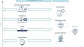
Figure 1 shows a snapshot of a range of MEMS accelerometers and classifies each sensor based on key performance metrics for a specific application and the level of intelligence/integration. A key focus for this article is on next-generation accelerometers based on enhanced MEMS structures and signal processing, along with world-class packaging techniques offering stability and noise performance comparable with more expensive niche devices, while consuming less power. These attributes and other critical accelerometer specifications are discussed in more detail in the following sections based on application relevance.

Figure 1. Application landscape for a selection of Analog Devices MEMS accelerometers.
Inclination or Tilt Sensing
Key criteria: Bias stability, offset over temperature, low noise, repeatability, vibration rectification, cross-axis sensitivity.
Accurate inclination or tilt sensing is a demanding application for MEMS capacitive accelerometers, especially in the presence of vibration. Using MEMS capacitive accelerometers to achieve 0.1° of tilt accuracy in dynamic environments is very difficult—<1° is difficult and >1° is very achievable. In order for an accelerometer to effectively measure tilt or inclination, the sensor performance and end application environment must be well understood. Static environments provide much better conditions for measuring inclination vs. dynamic environments, because vibration or shock can corrupt tilt data and lead to significant errors in measurements. The most important specifications for measuring tilt are tempco offset, hysteresis, low noise, short-/long-term stability, repeatability, and good vibration rectification.
Errors such as zero-g bias accuracy, zero-g bias shift due to soldering, zero-g bias shift due to PCB enclosure alignment, zero-g bias tempco, sensitivity accuracy and tempco, nonlinearity, and cross-axis sensitivity are observable and can be reduced through postassembly calibration processes. Other error terms such as hysteresis, zero-g bias shift over life, sensitivity shift over life, zero-g shift due to humidity, and PCB bend and twist due to temperature variations over time can’t be addressed in calibration, or else they require some level of in-situ servicing to be reduced.
Analog Devices’ range of accelerometers can be divided into MEMS (ADXLxxx) and iSensor (ADIS16xxx) special purpose parts. iSensor or intelligent sensors are highly integrated (4° to 10° of freedom) and programmable parts used in complex applications under dynamic conditions. These highly integrated plug-and-play solutions include full factory calibration, embedded compensation, and signal processing—solving many of the errors outlined above for in-situ servicing and greatly reducing the design and verification burden. This extensive factory calibration characterizes the entire sensor signal chain for sensitivity and bias over a specified temperature range, typically −40°C to +85°C. As a result, each iSensor part has its own unique correction formulas to produce accurate measurements upon installation. For some systems, the factory calibration eliminates the need for system-level calibration and greatly simplifies it for others.
iSensor parts are specifically targeted at certain applications. For example, the ADIS16210 shown in Figure 2 was designed and tailored specifically for inclination applications and, as a result, can offer <1° relative accuracy out of the box. This is largely down to the integrated signal processing and unit specific calibration for optimal accuracy performance. iSensors are discussed further in the stabilization section.

Figure 2. ADIS16210 precision triaxial inclination.
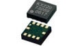
Latest generation accelerometer architectures such as the ADXL355 are more versatile (inclination, condition monitoring, structural health, IMU/AHRS applications) and contain less application specific, but still feature-rich integrated blocks, as shown in Figure 3.

Figure 3. ADXL355 low noise, low drift, low power, 3-axis MEMS accelerometer.
The following section compares the ADXL345, a general-purpose accelerometer, with the next-generation low noise, low drift, and low power ADXL355 accelerometer, which is ideal for use in a wide range of applications, such as IoT sensor nodes and inclinometers. This comparison looks at error sources in a tilt application and what errors can be compensated or removed. Table 2 shows an estimate of the consumer grade ADXL345 accelerometers ideal performance specifications and the corresponding tilt errors. When trying to achieve the best possible tilt accuracy, it is imperative to apply some form of temperature stabilization or compensation. For this example, a constant temperature of 25°C is assumed. The largest error contributors that can’t be fully compensated out are offset over temperature, bias drift, and noise. Bandwidth can be lowered to reduce the noise, as inclination applications typically require bandwidths below 1 kHz.
| Sensor Parameter | Performance | Condition/Note | Typical Application Error g Tilt ° |
| Noise | X/Y axis 290 μg/√(Hz) | Bandwidth at 6.25 Hz | 0.9 mg / 0.05° |
| Bias drift | Allan deviation | X/Y axis short-term (Ex: 10 days) | 1 mg / 0.057° |
| Initial offset | 35 mg | No compensation OR With compensation | 35 mg / 2° OR 0 mg / 0° |
| Error | No compensation | 6.25 Hz bandwidth | 36.9 mg / 2.1° |
| Error | With compensation | 6.25 Hz bandwidth | 1.0 mg / 0.1° |
Table 3 shows the same criteria for the ADXL355. Short-term bias values were estimated from the root Allan variance plots in the ADXL355 data sheet. At 25°C, the compensated tilt accuracy is estimated as 0.1° for the general-purpose ADXL345. For the industrial grade ADXL355, the estimated tilt accuracy is 0.005°. Comparing the ADXL345 and ADXL355, it can be seen that large error contributors like noise have been reduced significantly from 0.05° to 0.0045° and bias drift from 0.057° to 0.00057°, respectively. This shows the massive leap forward in MEMS capacitive accelerometer performance in terms of noise and bias drift—enabling much higher levels of inclination accuracy under dynamic conditions.
| Sensor Parameter | Performance | Condition/Note | Typical Application Error g Tilt ° |
| Noise |
X/Y axis 290 μg/√(Hz |
Bandwidth at 6.25 Hz | 78 μg / 0.0045° |
| Bias drift | Allan deviation | X/Y axis short-term (Ex: 10 days) | <10 μg / 0.00057° |
| Initial offset | 25 mg | No compensation OR With compensation | 25 mg / 1.43° OR 0 mg / 0° |
| Total error | No compensation | 6.25 Hz bandwidth | 25 mg / 1.43° |
| Total error | With compensation | 6.25 Hz bandwidth | 88 μg / 0.005° |
The importance of selecting a higher grade accelerometer is crucial in achieving the required performance, especially if your application demands below 1° of tilt accuracy. Application accuracy can vary depending on application conditions (large temperature fluctuations, vibration) and sensor selection (consumer grade vs. industrial or tactical grade). In this case, the ADXL345 will require extensive compensation and calibration effort to achieve <1° tilt accuracy, adding to the overall system effort and cost. Depending on the magnitude of vibrations in the end environment and temperature range, this may not even be possible. Over 25°C to 85°C, the tempco offset drift is 1.375°—already exceeding the requirement for less than 1° of tilt accuracy:

For the ADXL355 the maximum tempco offset drift from 25°C to 85°C is 0.5°.

The ADXL354 and ADXL355 repeatability (±3.5 mg/0.2° for X and Y, ±9 mg/0.5° for Z) is predicted for a 10 year life and includes shifts due to the high temperature operating life test (HTOL) (TA = 150°C, VSUPPLY = 3.6 V, and 1000 hours), temperature cycling (−55°C to +125°C and 1000 cycles), velocity random walk, broadband noise, and temperature hysteresis. By providing repeatable tilt measurement under all conditions, these new accelerometers enable minimal tilt error without extensive calibration in harsh environments, as well as minimize the need for post-deployment calibration. The ADXL354 and ADXL355 accelerometers offer guaranteed temperature stability with null offset coefficients of 0.15 mg/°C (maximum). The stability minimizes resource and expense associated with calibration and testing effort, helping to achieve higher throughput for device OEMs. In addition, the hermetic package helps ensure that the end product conforms to its repeatability and stability specifications long after it leaves the factory.
Typically, repeatability and immunity to vibration rectification error (VRE) are not shown on data sheets, due to being a potential indicator of lower performance. For example, the ADXL345 is a general-purpose accelerometer targeted at consumer applications where VRE is not a key concern for designers. However, in more demanding applications such as inertial navigation, inclination applications, or particular environments rich in vibration, immunity to VRE is likely to be a top concern for a designer and, hence, its inclusion on the ADXL354/ADXL355 and ADXL356/ADXL357 data sheets.
VRE, as shown in Table 4, is the offset error introduced when accelerometers are exposed to broadband vibration. When an accelerometer is exposed to vibrations, VRE contributes significant error in tilt measurements when compared to 0 g offset over temperature and noise contributions. This is one of the key reasons it is left off data sheets, as it can very easily overshadow other key specifications.
VRE is the response of an accelerometer to ac vibrations that get rectified to dc. These dc rectified vibrations can shift the offset of the accelerometer, leading to significant errors, particularly in inclination applications where the signal of interest is the dc output. Any small change in dc offset can be interpreted as a change in inclination and lead to system-level errors.
| Part | Maximun Tilt Error 0 g Offset vs. Temperature (°/°C) | Noise Density (°/√(HZ)) | Vibration Rectification (°/g 2 rms) |
| ADXL345 | 0.0085 | 0.0011 | 0.0231 |
| ADXL355 | 0.0085 | 0.0014 | 0.0231 |
(1 ±2 g range, in a 1 g orientation, offset due to 2.5 g rms vibration.)
VRE can be caused by various resonances and filters within the accelerometer, in this case, the ADXL355, due to VRE having a strong dependence on frequency. The vibrations are amplified by these resonances by a factor equal to the Q factor of the resonance and will damp vibrations at higher frequencies, due to the 2nd order of the resonator’s 2-pole response. The greater the sensor’s Q factor resonance, the greater the VRE due to larger amplification of the vibrations. Larger measurement bandwidth leads to the integration of high-frequency in-band vibrations, leading to higher VRE, as shown in Figure 4. Many vibration related issues can be avoided by choosing an appropriate bandwidth for the accelerometer to reject high-frequency vibrations.1

Figure 4. ADXL355 VRE test at different bandwidths.
Static tilt measurements typically require low g accelerometers around ±1 g to ±2 g, with bandwidths less than 1.5 kHz. The analog output ADXL354 and the digital output ADXL355 are low noise density (20 μg√Hz and 25 μg√Hz respectively), low 0 g offset drift, low power, 3-axis accelerometers with integrated temperature sensors and selectable measurement ranges, as shown in Table 5.
| Part | Measurement Ranges (g) | Bandwidth (kHz) |
| ADXL354B | ±2, ±4 | 1.5 |
| ADXL354C | ±2, ±8 | 1.5 |
| ADXL355B | ±2, ±4, ±8 | 1 |
| ADXL356B | ±10, ±20 | 1.5 |
| ADXL356C | ±10, ±40 | 1.5 |
| ADXL357B | ±10.24, ±20.48, ±40.96 | 1 |
ADXL354/ADXL355 and ADXL356/ADXL357 come in a hermetic package, helping to provide excellent long-term stability. Performance gains due to package typically scale, as shown in Figure 5. The package is often overlooked in terms of what a manufacturer can do to add extra performance in relation to stability and drift. This has been a key focus of Analog Devices, which can be seen across the wide array of sensor package types we offer to fit varying application areas.
High Temperature and Dynamic Environments
Before the availability of accelerometers rated for high temperature or harsh environment operation, some designers were forced to use standard temperature ICs well beyond data sheet limits. This means the end user takes on the responsibility and risk of qualifying the component at elevated temperatures, which is expensive and time-consuming. Sealed hermetic packages have been well known to be robust at elevated temperatures and provide a barrier against moisture and contamination that cause corrosion. Analog Devices offer a range of hermetically sealed parts offering enhanced stability and performance over temperature.
Analog Devices has also done significant work examining the performance of plastic packages at elevated temperatures—in particular, the lead frame and leads ability to comply with high temperature soldering processes and providing secure attachment for high shock and vibration environments. As a result, Analog Devices offers 18 accelerometers with a specified temperature range of −40°C to +125°C including ADXL206, ADXL354/ADXL355/ADXL356/ADXL357, ADXL1001/ADXL1002, ADIS16227/ADIS16228, and ADIS16209. Most competitors do not offer MEMS capacitive accelerometers capable of performing over −40°C to +125°C or in harsh environmental conditions, such as heavy industrial machinery and down-hole drilling and exploration.

Figure 5. Examples of performance gains due to advanced packaging techniques and calibration.
Performing inclination measurements in very harsh environments with temperatures above 125°C is an extremely challenging task. The ADXL206 is a high precision (tilt accuracy <0.06°), low power, complete, dual-axis MEMS accelerometer for use in high temperature and harsh environments, such as down-hole drilling and exploration. This part comes in a 13 mm × 8 mm × 2 mm side-brazed, ceramic, dual in-line package, which allows for an ambient temperature range of −40°C to +175°C, with diminishing performance above 175°C with 100% recoverability.
Inclination measurements in dynamic environments where vibration is present, such as agricultural equipment or drones, require higher g-range accelerometers such as the ADXL356/ADXL357. Accelerometer measurements in a limited g-range can lead to clipping, which results in extra offset being added to the output. Clipping could be due to the sensitive axis being in the 1 g field of gravity or due to shocks with fast rise times and slow decay. With a higher g-range, accelerometer clipping is reduced, thus reducing offset leading to better inclination accuracy in dynamic applications.
Figure 6 shows a g-range limited measurement from the ADXL356 Z-axis, with 1 g already being present in this range of measurement. Figure 7 shows the same measurement but with the g-range extended from ±10 g to ±40 g. It can be clearly seen that the offset due to clipping is significantly reduced by extending the g-range of the accelerometer.
The ADXL354/ADXL355 and ADXL356/ADXL357 offer superior vibration rectification, long-term repeatability, and low noise performance in a small form factor and are ideally suited for tilt/inclination sensing in both static and dynamic environments.

Figure 6. ADXL356 VRE, Z-axis offset from 1 g, ±10 g-range, Z-axis orientation = 1 g.

Figure 7. ADXL356 VRE, Z-axis offset from 1 g, ±40 g-range, Z-axis orientation = 1 g.
Stabilization
Key criteria: Noise density, velocity random walk, in-run bias stability, bias repeatability, and bandwidth.
Detecting and understanding motion can add value to many applications. Value arises from harnessing the motion that a system experiences and translating it into improved performance (reduced response time, higher precision, faster speed of operation), enhanced safety or reliability (system shut-off in dangerous situations), or other added-value features. There is a large class of stabilization applications that require the combination of gyroscopes with accelerometers (sensor fusion), as shown in Figure 8, due to the complexity of motion—for example, in UAV-based surveillance equipment and antenna pointing systems used on ships.2

Figure 8. Six degrees of freedom IMU.
Six degrees of freedom IMUs use multiple sensors so they can compensate for each other’s weaknesses. What may seem like simple inertial motion on one or two axes can actually require accelerometer and gyroscope sensor fusion, in order to compensate for vibration, gravity, and other influences that an accelerometer or gyroscope alone would not be able to accurately measure. Accelerometer data consists of a gravity component and motion acceleration. These cannot be separated, but a gyroscope can be used to help remove the gravity component from the accelerometer output. The error due to the gravity component of the accelerometer data can quickly become large after the required integration process to determine the position from acceleration. Due to accumulating error, a gyroscope alone is not sufficient for determining position. Gyroscopes do not sense gravity, so they can be used as a support sensor along with an accelerometer.
In stabilization applications, the MEMS sensor must provide accurate measurements of the platforms orientation, particularly when it is in motion. A block diagram of a typical platform stabilization platform system utilizing servo motors for angular motion correction is shown in Figure 9. The feedback/servo motor controller translates the orientation sensors data into corrective control signals for the servo motors.

Figure 9. Basic platform stabilization system.3
The end application will dictate the level of accuracy required, and the quality of sensor chosen whether consumer or industrial grade will determine whether this is achievable or not. It is important to distinguish between consumer-grade devices and industrial grade devices, and this can sometimes require careful consideration as the differences can be subtle. Table 6 shows the key differences between a consumer grade and midlevel industrial grade accelerometer integrated into an IMU.
| Accelerometer Parameter | Typical Industrial Specification | Improvement Over Typical Consumer Device |
| Dynamic range | Up to 40 g | 3× |
| Noise density | 25 μg/√Hz | 10× |
| Velocity random walk | 0.03 m/s/√Hz | 10× |
| In-run bias repeatability | 10 μg | 10× |
| Bias repeatability | 25 mg | 100× |
| -3 dB bandwidth | 500 Hz | 2× |
In some cases where conditions are benign and imprecise data is acceptable, a low precision device can provide adequate performance. However, the demands on the sensor in dynamic conditions grow rapidly and lower precision parts suffer greatly due to not being able to reduce vibration effects from actual measurements or temperature effects, therefore struggling to measure below 3° to 5° of pointing accuracy. Most low-end consumer devices do not provide specifications for parameters such as vibration rectification, angular random walk, and other parameters that actually can be the largest error sources in industrial applications.
In order to measure from 1° down to 0.1° of pointing accuracy in dynamic environments, a designer’s part selection must focus on the sensors ability to reject drift error over temperature and vibration influences. While sensor filtering and algorithms (sensor fusion) are a critical element in achieving improved performance, they are not capable of eliminating performance gaps from a consumer grade to industrial grade sensor. Analog Devices new class of industrial IMUs achieve performance close to what was used in previous generation missile guidance systems. Parts such as the ADIS1646x and the announced ADIS1647x can provide precision motion sensing in standard and mini IMU form factors, opening up what used to be a niche application area.
In part 2 of this article we will continue to explore key performance characteristics of MEMS accelerometers and how to they relate to applications areas such as wearable devices, condition-based monitoring, and IoT, including structural health monitoring and asset health monitoring.
References
¹ Long Pham and Anthony DeSimone. “Vibration Rectification in MEMS Accelerometers.” Analog Devices, Inc., 2017
² Bob Scannell. “High-Performance Inertial Sensors Propelling the Internet of Moving Things.” Analog Devices, Inc., 2017.
³ Mark Looney. “Analyzing Frequency Response of Inertial MEMS in Stabilization Systems.” Analog Dialogue, Vol. 46, 2012.