Facebook
 Google
 GitHub
 Linkedin
Configuring a SparkFun Power Delivery Board using a FixturFab DEV260
The FixturFab DEV260 development fixture allows designers to debug or configure PCBAs during the development phase. See how it works in this example using the Sparkfun Power Delivery Board.
The FixturFab DEV260 Development Fixture is a simple fixture used for debugging or configuring PCBAs during development. In this case study, we cover how a DEV260 fixture can be created to configure a SparkFun Power Delivery Board. These same techniques can be used to create a fixture for programming, debugging, or configuring your custom PCBA.
About the Sparkfun Power Delivery Board
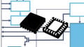
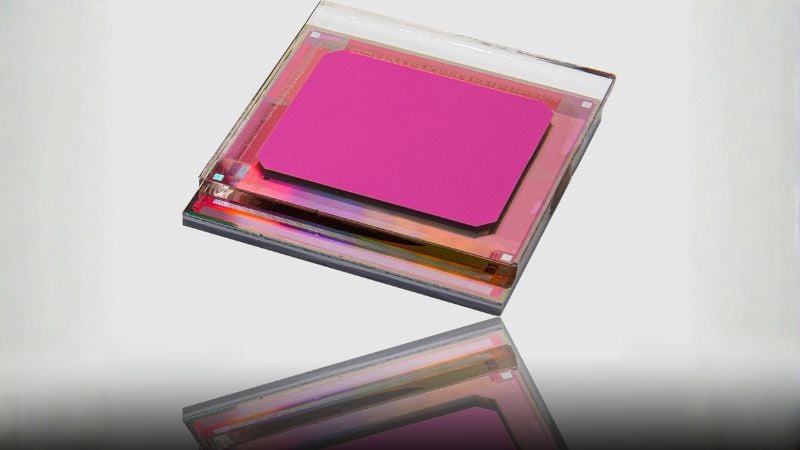
The SparkFun Power Delivery Board takes advantage of the power delivery standard with the use of a standalone controller from STMicroelectronics, the STUSB4500.

Figure 1. SparkFun Power Delivery Board
The STUSB4500 is a USB power delivery controller that addresses sink devices. It implements a proprietary algorithm to allow the negotiation of a power delivery contract with a source (i.e. a power delivery wall wart or power adapter) without the need for an external microcontroller. However, you will need a microcontroller to configure the board. PDO profiles are configured in an integrated non-volatile memory. The controller does all the heavy lifting of power negotiation and provides an easy way to configure over I2C.
To configure this device using I2C, SparkFun recommends using their Qwiic system, however, this requires using a connector to configure each device. To easily configure multiple Power Delivery boards (i.e., for a small production run), a simple bed of nails test fixture can be used.

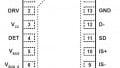
Figure 2. Test points for configuring the power delivery board
To configure the board using a bed of nails fixture, the following nets will need to be accessed:
- GND
- VDD
- SDA
- SCL
These nets will be accessed using Test Probes (Pogo-Pins), which will be connected to a Binho Nova Host Adapter, which will perform the actual configuration.
Designing the Test Fixture
The FixturFab Design Platform can be used to easily design a DEV260 Development Fixture for the SparkFun Power Delivery Board. The platform can be accessed by creating a FixturFab account.
To start the design process, we will create a new project and enter the project name, PCB thickness for the SparkFun Power Delivery Board, and upload the ECAD design file. FixturFab supports Eagle’s .brd files, KiCAD’s .kicad_pcb files, Altium Test Point CSV reports, and Gerber files from any other EDA software.
Click the Create Project button to proceed.

Figure 3. Creating a new FixturFab project
The fixture type can then be selected. For this project, we will use the DEV260 Fixture.

Figure 4. Selecting fixture type
The parsed test point information from the ECAD file will then be displayed. The PCB board width and height are automatically detected, but you should always verify that these values are correct.

Figure 5. Project settings
Adding Test Pins
The test points can then be configured for the project. While we only need the four test points that were shown above, we will include all of the detected test points in this fixture. This will allow us to wire it for other uses, such as functional testing, in the future.
For each test point, the Receptacle and Test Probe need to be configured. A receptacle is a metal tube that mounts into the probe plate of the test fixture and is wired to the Binho Nova. The test probe (pogo-pin) is spring-loaded and mounted inside of the test receptacle.

Figure 6. An Ingun test probe, receptacle, and wire.
These test probes contact the PCBA, also referenced as the Device Under Test or DUT, creating an interface between the board and test instrumentation. Using receptacles allows for broken test probes to be easily replaced.
For this fixture, we will use R75-1W receptacles and P75-LM1 test probes.

Figure 7. Configured test points
Adding Guide Pins
To locate the Power Delivery Board within the fixture, Spring Guide Pins will be used on the four mounting holes on the PCB as shown below.

Figure 8. Guide pin locations on the SparkFun Power Delivery Board.
FixturFab identified the four mounting holes, as well as the 16 “mousebites” that are on the PCB. The mounting holes can be identified by their diameter of 3.3mm. Disable all of the mouse bites, and then select GP-2 Spring Guide Pins from the Pin Selection dropdown.

Figure 9. Configured guide pins
Adding Pressure Pins
Pressure pins also need to be added to the fixture. These pins are used to push on the top of the PCB to press it against the Spring Guide Pins and Test Probes within the fixture. The pressure pins that are available on FixturFab have a tip diameter of 3mm. To determine the locations of the pins, we can use the ECAD design software and place a 3mm circle in a location where it will not interfere with any other parts.

Figure 10. Pressure pin locations (in blue)
Add the coordinates for the pressure pins and select the 6x45mm Pressure Pin, 3mm Tip type.

Figure 11. Configured pressure pins
Final Adjustments
All of the components for the fixture have now been added. Click Next to view a 3D render of the fixture and configure the location of the Device Under Test (DUT).

Figure 12. Render of the Test Fixture
The location, rotation, and panel configuration of the DUT can now be configured. By default, the DUT is placed near the center of the fixture, with a panel configuration of 1 device.
The following changes can be made:
- Test point Layer
- Top/Bottom of the PCB, select which layer you like to have contacted by the test probes.
- If Top is selected, the test points are mirrored, so that the PCBA can be inserted upside down
- Top/Bottom of the PCB, select which layer you like to have contacted by the test probes.
- DUT Rotation
- Rotation of the PCB
- X-Offset
- Add an offset to the DUT X location, this is used to center the PCBA within the fixture.
- +X moves the DUT X millimeters to the right
- -X moves the DUT X millimeters to the left
- Y-Offset
- Add an offset to the DUT Y location, this is used to center the PCBA within the fixture
- +Y moves the DUT Y millimeters towards the back of the fixture
- -Y moves the DUT Y millimeters towards the front of the fixture
- Panel Settings
- If a panel of PCBA’s will be tested at the same time within the fixture, these settings can be used to configure the panel
Add offsets so that the DUT is centered in the X-axis, and towards the front of the fixture (Y-axis).

Figure 13. Configured DUT location
After making all the necessary adjustments, click Generate Fixture. A summary of the fixture design will then be shown.

Figure 14. Summary of the Test Fixture Project
Note: The fixture design can be purchased by sending an email to support@fixturfab.com, if you are following along with this case study, feel free to send us an email as well and we can unlock the design files for you.
After purchasing the fixture, FixturFab will perform a design review, and then fabricate, assemble, and ship the test fixture. This entire process takes approximately five days.
Wiring the DEV260 Fixture
After receiving the fixture, the Binho Nova will need to be connected to the test probes before a SparkFun Power Delivery Board can be configured.

Figure 15. Bottom of the probe plate on the SparkFun Power Delivery DEV260 fixture
We’ll use female to male jumper wires and a breadboard to connect the P75-1W test receptacles to the test instrumentation. Attach the Binho Nova and breadboard to the bottom plate of the fixture using double-sided tape. Then use jumper wires to connect the 3V3, GND, SCL, and SDA test probes to the Binho Nova.

Figure 16. Wired SparkFun Power Delivery Board DEV260 fixture
The bottom plate can then be placed back on the fixture.
Configuring the Sparkfun Power Delivery Board
The fixture is now complete, however, without any software to control the Binho Nova, the fixture is functionally useless.
To run test scripts on the fixture, we recommend using Python and pytest. Binho has a tutorial on how to use pytest, and this approach can be extended to work with any test fixture and instrumentation that you are using.
For this project, an example project is available. To run this project, you will need to have Python 3.6+ and pip installed.
Clone the repository and install the requirements
git clone https://gitlab.com/fixturfab-example-projects/sparkfun-usbc-pd-test-demo.git
cd sparkfun-usbc-pd-test-demo
pip install -r requirements.txt
To run the tests, place a SparkFun Power Delivery Board in the fixture.

Figure 17. SparkFun Power Delivery Board in the DEV260 test fixture
Run the tests using pytest.
pytest -x
The tests should then run which configure the SparkFun Power Delivery Board and display the following after a successful execution.
~/PycharmProjects/sparkfun-usbc-pd-test-demo # pytest
======================================= test session starts ================================
platform linux -- Python 3.8.2, pytest-5.4.3, py-1.9.0, pluggy-0.13.1
rootdir: ~/PycharmProjects/sparkfun-usbc-pd-test-demo
collected 21 items
test_sparkfun_usbc_pd/test_config_stusb4500.py .....................
[100%]
======================================= 21 passed in 6.65s =================================
Summary
In this case study, we demonstrated using FixturFab to design a DEV260 Development Fixture that can be used to configure and test a PCBA. These same methods can be used to create fixtures to help test your product throughout the development process. Because of their low cost and quick turn-around, we believe these are valuable tools for EVT and DVT.