 Facebook
 Google
 GitHub
 Linkedin
Designing Wearable Injectors: Low Power Meets Circuit Protection
Learn how to optimize performance, safety, and battery life in 24/7 drug delivery systems using smart sensing and protection components.
Wearable medicine injectors are enabling round-the-clock patient care—no hospital required. But engineering these compact devices is no small task. Designers must pack high-reliability electronics, wireless connectivity, and safety-critical functions into a lightweight, battery-powered form factor.
For devices that must operate 24/7 without failure, engineers face a design challenge trifecta: maximizing battery life, shrinking the circuit footprint, and safeguarding against electrical hazards.
This article examines how component-level choices—ranging from resettable fuses and eFuses to TVS diodes and TMR switches—can enable engineers to build smarter, more reliable drug delivery systems. Block diagrams and real-world examples illustrate strategies for balancing power efficiency with robust circuit protection in space-constrained medical applications.
Connected Drug Delivery Systems
As shown in Figure 1, modern drug delivery systems are wearable, wirelessly connected, and tailored for individual patient needs. Their design must enable continuous operation without compromising safety or usability.
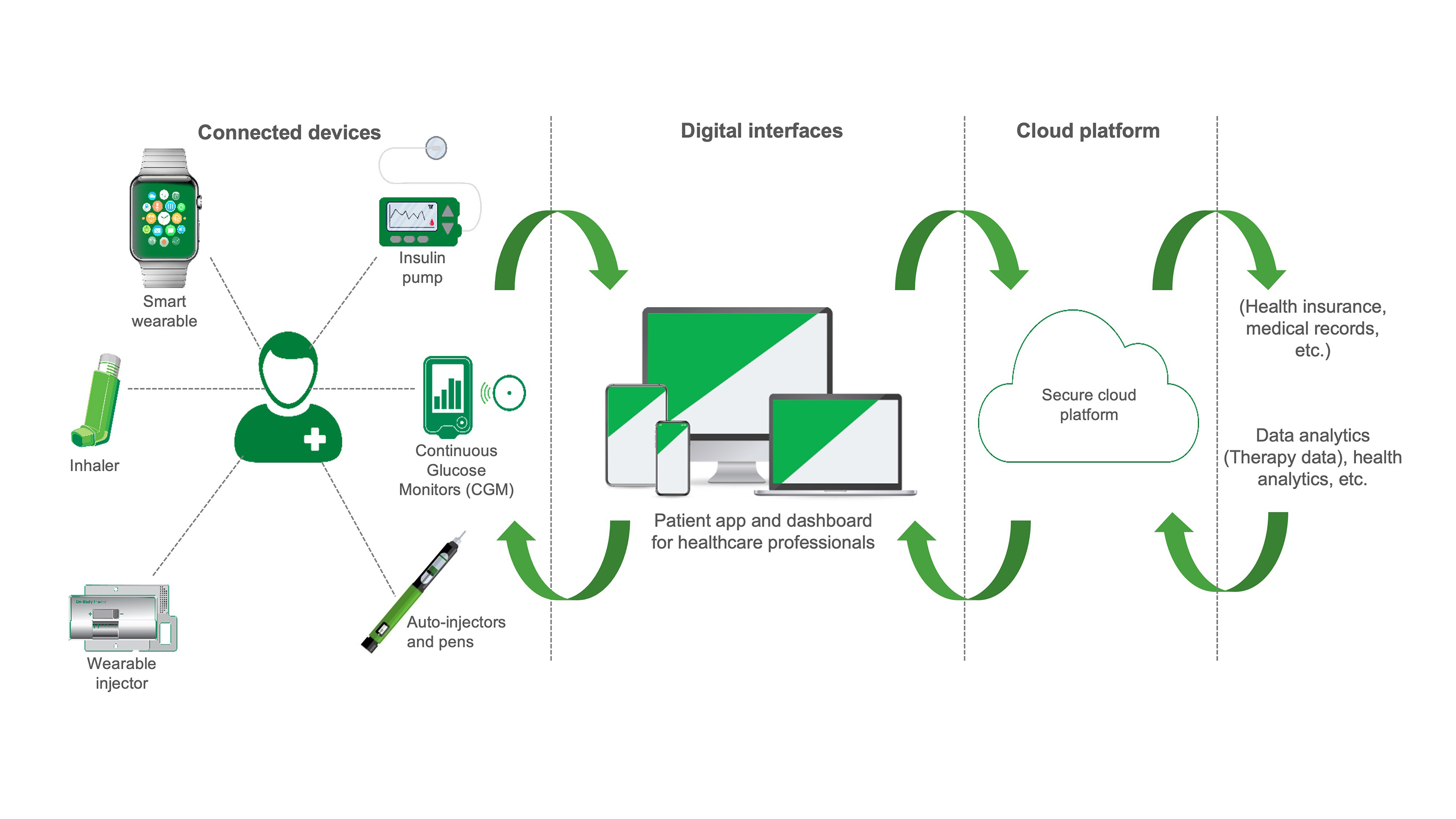
Figure 1. Connected drug delivery capabilities in the medtech ecosystem. (Click on image to enlarge)
Understanding the Architecture: Wearable Drug Delivery System
Figure 2 presents a conceptual view of a typical wearable medicine injector. It highlights core functional blocks—power management, dose dialing, motor control, etc.—along with recommended protection and control components. This visual helps engineers understand where to implement protection against electrical hazards and where to integrate low-power sensing options.
Figure 2 provides a comprehensive look at how protection and sensing components integrate within the system. It complements the block-level diagram in Figure 3. Engineers can use this as a reference when mapping out protection and sensing functions on the PCB.
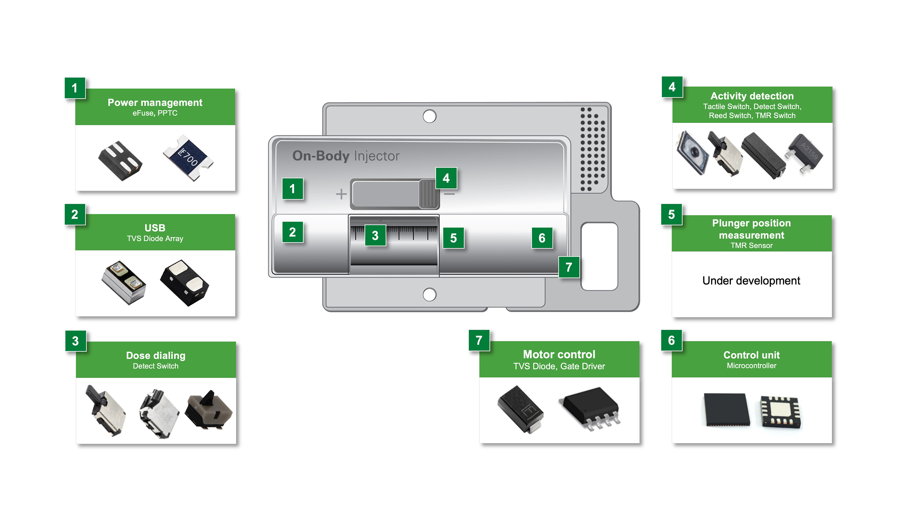
Figure 2. Wearable medicine injector example and recommended protection and control components. (Click on image to enlarge)
Figure 3, meanwhile, provides a more detailed block diagram of the same system, mapping specific circuit functions (for example, USB input, dose delivery sensing, activity detection) to the corresponding protection and control components. A reference table adjacent to the diagram outlines recommended solutions for each block—such as PPTC resettable fuses for USB-A/B ports, eFuse ICs for USB-C, and TVS diodes for motor and ESD protection.
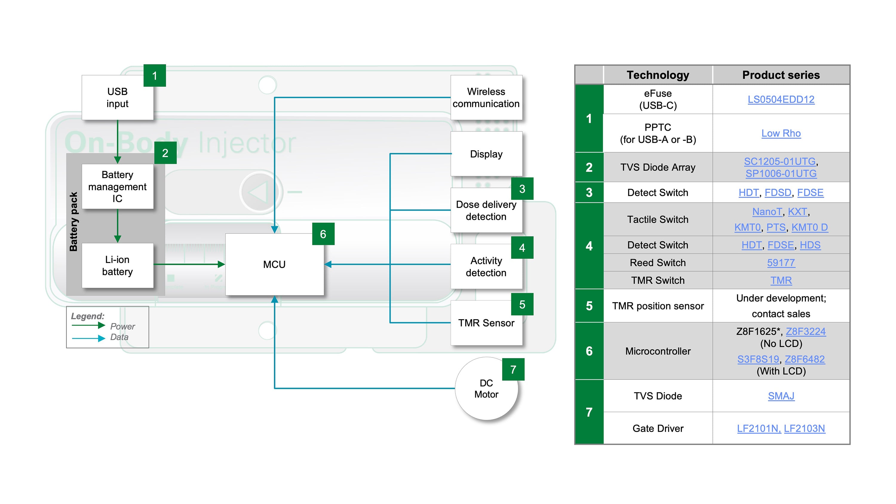
Figure 3. Wearable medicine injector block diagram. (Click on image to enlarge)
Power Input Protection: PPTC and eFuse
Power input—especially USB charging—is a critical vulnerability in these devices. A Li-ion battery supplies the system, which is recharged via USB-A, USB-B, or USB-C, depending on the power requirements. For USB-A/B input protection, PPTC resettable fuses are the preferred choice. These surface-mount fuses offer low resistance (<1 Ω) and conserve board space while limiting fault current during overcurrent events.
For designs using USB-C, engineers can implement a compact eFuse IC that integrates overvoltage, overcurrent, and overtemperature protection in one 4-pin DFN package. Figure 4 shows the block diagram of the LS0504EDD12, a Littelfuse eFuse Load Switch rated for 5.5 V and 4 A. The device includes a soft-start circuit to minimize inrush, an undervoltage lockout to protect against brownouts, and a 26 mΩ low RDS(on) internal switch to reduce conduction losses. This compact IC eliminates the need for multiple discrete protection components.
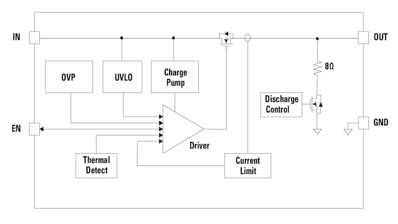
Figure 4. Low-RON eFuse 5.5 V, 4 A load switch (LS0504EDD12)
Subsystem by Subsystem
Now let’s examine each subsystem one by one.
Battery Management and ESD Protection
Battery Management ICs monitor state-of-charge (SoC) and state-of-health (SoH), essential for ensuring long battery life and safe operation. These sensitive circuits require robust protection from electrostatic discharge (ESD). Designers can use bidirectional TVS diode arrays to suppress ±30 kV ESD strikes. These arrays react within nanoseconds, clamping voltage to safe levels without interfering with normal operation.
Motor Drive Protection
Motor drivers that control the injector plunger or dial mechanism are susceptible to both power surges and ESD. Surface-mount TVS diodes rated for 400 W of surge power and 30 kV ESD provide effective protection in both unidirectional and bidirectional configurations. Their ultra-fast response (<1 ps) ensures the safety of motor control circuitry without degrading efficiency.
Display and Wireless Circuit Safeguards
Display and RF circuitry—especially Bluetooth Low Energy (BLE) and Zigbee—require protection that won’t distort signal integrity. Low-capacitance TVS diodes prevent ESD damage without introducing capacitance-related distortion, which can compromise RF performance or data accuracy.
Compact Sensing for Precision and Safety
In wearable injectors, sensing functions monitor device placement, skin contact, and dose delivery. These sensors must be ultra-compact, low-power, and highly reliable.
Dose Delivery Detection
This subsystem requires a mechanical detect switch to confirm plunger position or dial settings. Engineers can use tactile detect switches with 3.5 × 2.8 mm footprints, 35 g actuation force, and lifespans over 100,000 cycles. Contact resistance stays low (500 mΩ), ensuring signal integrity with minimal power loss.
Activity Detection and Skin Contact Verification
This circuit block ensures that the injector is properly seated on the skin and that the medication vial is present. Available solutions include:
-
Low-profile pushbutton switches: Surface-mount, IP67-rated, a height of 0.55 mm, and lifespans exceeding 300,000 cycles.
- Reed switches: Hermetically sealed and magnetically activated with virtually zero current draw—perfect for ultra-low-power systems.
- Detect switches: The same models used for dose delivery can be repurposed for contact sensing.
TMR Technology
A more advanced solution is the TMR (Tunneling Magnetoresistance) switch, shown in Figure 5. These switches use a magnetically sensitive junction to trigger a CMOS logic-level output. TMR switches like the one illustrated draw just 200 nA and can detect fields as low as 5 Gauss—ideal for monitoring the motion of the plunger in wearable injectors.
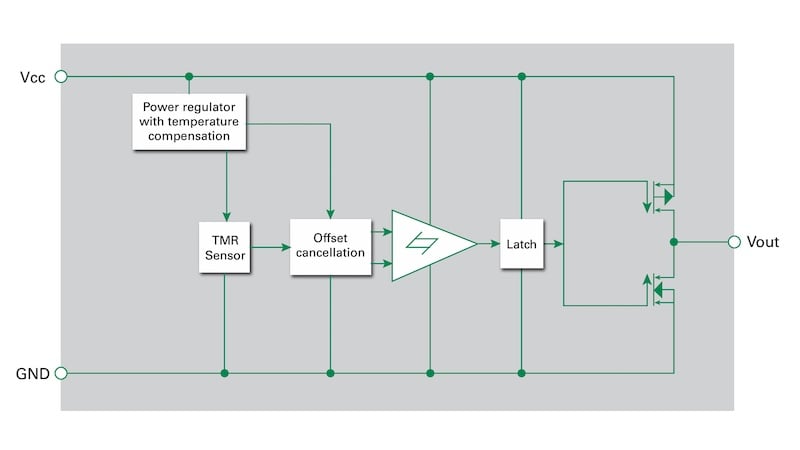
Figure 5. Integrated switch with tunneling magnetoresistance sensor and drive circuitry.
Placed near the bottom of the plunger chamber, the TMR switch responds as a magnet, mounted to the plunger, approaches. The microcontroller interprets the output voltage change to calculate the injection volume in real-time. This solution offers unmatched energy efficiency and precision.
Future Technologies
Two technologies are under development for direct and more accurate measurement of injected liquid volume. One technology employs a new TMR sensor for plunger position measurement. A second technology uses a capacitive sensor and an electrode on the pen that is not in contact with the cartridge.
The electrode features a unique patent-pending design. TMR and capacitive sensing can provide a more reliable and accurate measurement of injection volume. These new innovative sensors will be available shortly.
Embedded Control with Low-Power MCUs
Microcontrollers serve as the brain of the device, managing sensors, motor drivers, and communication. Engineers should select 8-bit or 32-bit MCUs optimized for low-power operation:
- Run current <2 mA
- Sleep current <1 µA
- On-chip ADCs and temperature sensors
- PWM timers for motor control
- Peripheral interfaces for BLE modules
Sleep modes significantly reduce power consumption when the device is inactive, extending the time between charges—especially critical for round-the-clock use.
Gate Drivers for Motor Efficiency
Motor efficiency also depends on the gate driver between the MCU and the MOSFET or IGBT. High-speed gate drivers with Schmitt-triggered inputs and 50 ns propagation delay ensure clean, responsive switching and reduce motor torque ripple. TTL and CMOS compatibility allows direct interface with MCU outputs.
Standards Compliance
All wearable medical injectors must meet stringent safety and performance standards. Table 1 summarizes key regulatory standards relevant to wearable injectors.
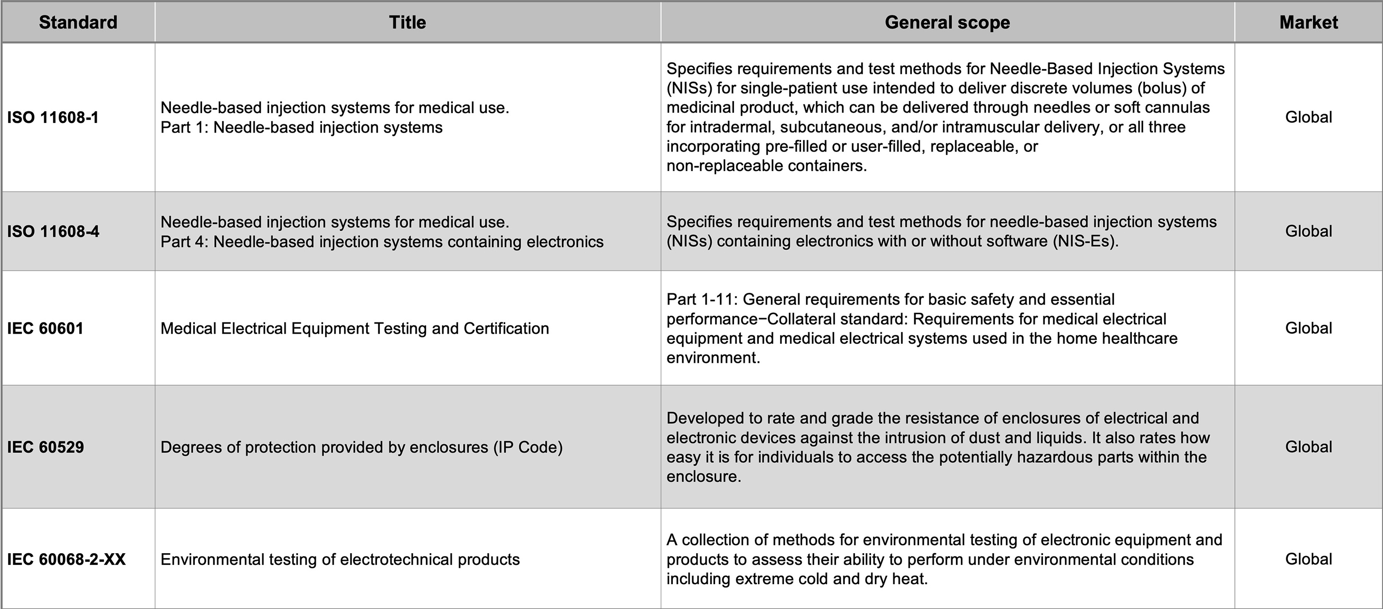
Table 1. Applicable standards for wearable medicine injectors. (Click on image to enlarge)
Early planning for certification—and partnering with vendors that offer pre-compliance support—can reduce redesigns and avoid delays during formal testing.
Combining Protection, Precision, and Power Efficiency
Developing a wearable medical injector involves complex trade-offs: space versus functionality, power versus responsiveness, and cost versus compliance. Component selection can dramatically influence all three.
From eFuses and TVS diodes to TMR switches and low-power MCUs, engineers have access to proven tools that deliver safety, efficiency, and durability in compact form factors. Partnering with component manufacturers that offer application guidance and pre-certification support can help teams avoid costly mistakes and accelerate time-to-market.
By combining robust protection strategies with efficient sensing and control techniques, designers can create next-generation wearable injectors that support improved patient outcomes across diverse healthcare environments, including the fast-growing medtech ecosystem.
Reference Literature
Portable Medical Devices Protection Quick Reference Guide
Switch Solutions for Medical Applications
Circuit Protection Product Selection Guide
Sensing Products Selection Guide
Battery Devices Short Form Catalog)
All images used courtesy of Littelfuse.


Very relevant insights. We’ve seen how accurate protection and low-power design can make or break reliability in wearable injectors. Used ITECH’s source measure units during validation—super helpful in catching subtle fault behaviors early on.