Measure Position and Speed Control of a DC Motor Using an Analog PID Controller
This article shows how to implement an analog PID controller, including adjusting of the angular position of a DC motor shaft, editing the design to control its speed, and tuning PID parameters for reliable performance.
This article shows how to implement an analog PID controller, including adjusting of the angular position of a DC motor shaft, editing the design to control its speed, and tuning PID parameters for reliable performance.
This article focuses on making an educational kit to demonstrate the effect of a PID controller on the response of a DC motor trying to reach a specific position, in this case, the zero position. The educational kit also can modify the PID control to adjust the motor speed to reach a specific desired speed, regardless of any reasonable load on the motor.
Main System Overview
The system is divided into three main parts:
- A rotary encoder, which relays the position of the DC motor shaft as an analog signal to be fed to the analog PID controller. This will be done using the Dialog SLG46621 programmable mixed-signal matrix IC.
- An analog PID controller with 3 potentiometers to control PID parameters. This takes an analog signal given from a point and sets the point as the zero position. This part then outputs an analog signal which controls the speed of the motor. This signal is not yet a PWM signal. This part of the system uses the quad op-amp SLG88104.
- A PWM generator that takes the analog signal that controls the speed of the motor and feeds it to the PWM block in our system. It then feeds the PWM block output to the motor driver to adjust the motor shaft to the desired position. Note that the direction of the motor is already known from the encoder feedback signals from part 1.
Typically, microcontrollers are used to implement PID controllers. They receive the input pulses from the encoder, then feed them through a control algorithm to output the motor speed. However, this requires software development and it can require a lot of time and money to develop a reliable system. A GreenPAK implementation doesn't require any software development or additional advanced hardware. Software-based PID has limitations depending upon which microcontroller you use. Conversely, hardware PID gives you more reliable control upon any parameter you want affecting your response, but hardware is typically harder to adjust.
For this solution to be viable as an educational kit several components are required:
- A well-designed enclosure with an on/off switch, wide control over PID parameters, and an additional LCD showing the parameter’s values.
- An adjustable PWM frequency from the GreenPAK PWM block for a smooth response.
- Stable mounting for the pointer attached to the motor.
Decoding the Incremental Rotary Encoder
The output of a rotary encoder is formed by two pulse signals which are 90º out of phase. The number of pulses correlates to the number of slots which the disk of the encoder covers upon one full rotation. The main idea of position control is that from our initial (zero) position we need to count the number of slots the disk will cover in either a CW or CCW direction. The count will then decrease if the disk reverses its direction. For example, if the motor started moving clockwise and counted 5 pulses (5 slots), then to go back to its initial position it needs to move 5 counts in the counterclockwise direction so that it ends up back where it started.
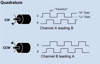
Figure 1. Quadrature encoder output
We will use pulse A and pulse B for position tracking and direction detection. An up/down counter has been implemented using GreenPAK blocks which will increase/decrease depending upon the direction of the motor. All of the blocks are synchronized through the internal oscillator.
First, I checked how many counts I needed to cover my scaling in one direction and I found that I needed about 30 counts according to my design. I used an 8-bit counter for improved precision. Then I implemented a direction detection circuit using a clocked quadrature decoder to determine if the motor was moving CW or CCW. The counter CNT4/DLY4/FSM1 is clocked every time there is a pulse on CW or CCW. A pulse on CW causes the counter to count up and a pulse on CCW causes the counter to count down. The counter is initialized to 127 (out of a max value of 255 to give it plenty of room to count up or down. The output is given via the SPI parallel output block to pins 12-20.
I implemented a clocked quadrature decoder using several DFFs and a pipe delay block. When A leads B there is a pulse on CW, and when B leads A there is a pulse on CCW. Then a final stage (DFF3) was added with CW as an input and CCW as a clock input so the inverted output of DFF3 remains LOW when the motor is rotating clockwise, and the output will remain HIGH when the motor is rotating counter-clockwise.
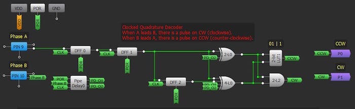
Figure 2. Clocked quadrature decoder using GreenPAK
The counter will hold the position of the rotary encoder until it is triggered up though a pulse on CW or down through a pulse on CCW. Note that the SLG46621 has 2 matrices: the 8-bit counter is implemented in the second matrix; the quadrature decoder circuit is implemented in the second matrix. The components required to generate the PWM signal are split between both matrices.
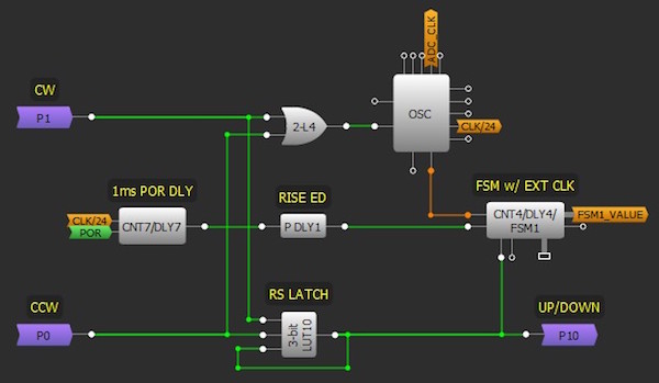
Figure 3. FSM up/down counter
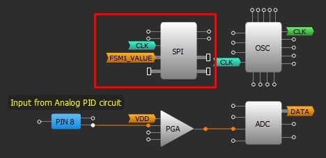
Figure 4. SPI block
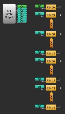
Figure 5. SPI parallel outputs
Converting Encoder Data into an Analog Signal
Now we have an 8-bit digital data value which needs to be converted to an analog signal so it can be fed into the analog PID. The built-in DAC doesn't support taking inputs directly from the CNT4/DLY4/FSM1 block so I implemented an external 8-bit DAC using a Dialog SLG88104 quad op-amp.
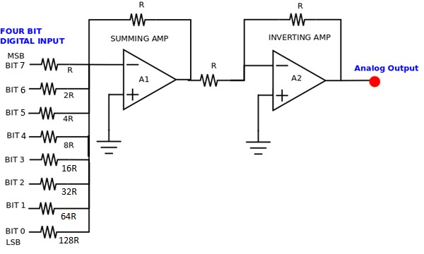
Figure 6. 8-bit DAC
I chose R to be 10 k ohm, bit 0 is SPI first parallel output which is pin 12 and so on. The resistor with the lowest value R corresponds to the highest weighted binary input Bit 7 (MSB) [27 = 128]. 2R, 4R, 8R,16R, 32R and 64 R correspond to the binary weights of Bit 6 (26 = 64), Bit 5 (25 = 32), Bit 4 (24 = 16), Bit 3 (23 = 8), Bit 2 (22 = 4), Bit 1 (21 = 2) and Bit 0 (LSB) [20 = 1] respectively. The relationship between the digital inputs (Bit 0 to Bit 7) and the analog output VOUT is as follows:

where VREF is the reference voltage of the circuit, which is 3.3 V for SLG46621. The summing amplifier is followed by an inverting amplifier to reverse the polarity of the voltage to get a positive voltage.
Note, that if you are using a dual supply op-amp your output will have two supply rails and will swing between +ve and -ve. You will have to make this output voltage positive by using another op-amp so that it can be fed to the PID circuit. If you are using a single supply op-amp your output will swing between GND and +ve VCC and you won't have to use a conversion circuit. In this case, because we are using SLG88104 op-amp, cases from 194 to 255 will be discarded as they are above 5 V - maximum voltage for the device.
In the results of this article, the DAC is implemented on a small breadboard.
Demonstration and Implementation of the PID Controller Using SLG88104
The term PID is an acronym that stands for Proportional Integral Derivative. A PID controller is part of a feedback system that uses Proportional, Integral, and Derivative drive elements to control a process.
PID control is needed because there are some things that are difficult to control using standard methods. A similar application was conducted to regulate the output of a power supply using a PIC microcontroller. The PIC reads the output voltage with an ADC converter and adjusts a PWM to regulate the output. The control strategy is simple: If the voltage is below a set-point, turn on the PWM. If the measured voltage is above the set-point, then turn off the PWM. The PIC power supply almost worked.
In practice, the PIC controller did produce the desired DC output voltage. Unfortunately, it also had a significant AC ripple riding on the DC signal.
This control strategy is called on-off or bang-bang control. Many types of systems use this control strategy. Take the furnace in your house as another example. When the temperature is below the set-point, the furnace is on. When the temp is above the set-point, the furnace is off. Just like the power supply, the plot of temperature over time results in a sine wave.
For some types of control, bang-bang is acceptable; for others, it’s not. You wouldn’t want this type of control for a servo motor, bad things would happen! Just imagine: the motor would be full power in one direction and, the next moment, full power in the other direction. You can see where the term bang-bang comes from; that servo won’t last long!
The PID controller can provide a controlled, almost-intelligent drive for systems. We will now examine the individual components of the PID system.
Proportional Controller
The proportional component is simply a gain block. The gain is set by the values of the resistors as follows:
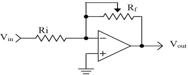
Figure 7. Proportional controller
Integral Controller
We can think of this as accumulating (adding) a quantity over time. In our PID controller, we are integrating voltage as time progresses. The output voltage is given by:
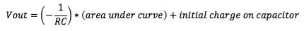
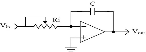
Figure 8. Integral controller
Area is a component of voltage and time. Let’s examine the operation of an ideal integrator. We can simplify the math by making the 1/RC term equal to 1 (i.e., let R=100 KΩ and C=10 µF).
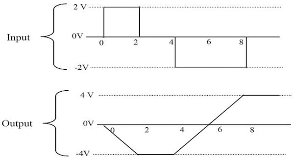
Figure 9. Relation between output and input in integral controller
In Figure 8, from 0 to 2 seconds, there is a 2 V square wave applied to the input of the integrator. The output of the integrator at the end of this time period is -4 V (remember the circuit is inverting). The integrator has accumulated a 2 V signal for 2 seconds. The area is equal to 4. From T2 to T4, there is no voltage applied to the integrator. The output is unchanged. In the remainder of this diagram, you can see that the integrator output changes polarity when the input signal changes polarity.
The previous discussion assumed an ideal integrator. Real capacitors will have some leakage and will tend to discharge themselves. Also, real OpAmps may charge the capacitor with no input present. If the circuit is built as drawn, it will likely saturate after a few minutes of operation. To prevent this saturation, add a resistor in parallel to the capacitor. For our purposes, we are not concerned about the saturation. We will be using the integrator with other circuits to control the charge on the capacitor.
Derivative Controller
The derivative is a measurement of the rate of change. This circuit looks similar to the high pass filters you have seen in other schematics. Low frequencies are attenuated, while high frequencies are allowed to pass. The output voltage is given by:
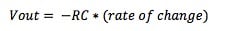
Rate of change is equivalent to measuring the slope of a line. Slope is a measure of the change in voltage divided by the change in time. In mathematical terms, this is referred to as a delta voltage over delta time or simply dv/dt. If we apply a ramp to the differentiator, we get a steady DC output voltage.
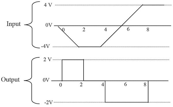
Figure 10. Relation between input and output in a derivative controller
To simplify the math, we will let RC=1. From time 0 to 2, the voltage changes -4 volts, while the time changes 2 seconds. The slope of this line is, therefore, -2. The output of the differentiator will be equal to 2 — remember the stage is inverting.
Using a PID Controller as a Position Controller in Applications
The first thing to notice is that this is a parallel process. The P, I, and D terms are calculated independently and then added at the summer Σ. The input to this loop is the set-point — in our application, 0 VDC is used as the zero position. The output is a signal which we will use to control the motor speed in the appropriate direction, as determined by the encoder. We will now examine each of the PID terms independently to see how they are related.
On the far left of Figure 11, we see a summing junction. The difference between the set-point and feedback is the error of the system. If the measured motor position is positive of where it should be, the error will be negative (i.e., a negative correction is required). Likewise, if the measured motor position is negative then a positive correction is required.
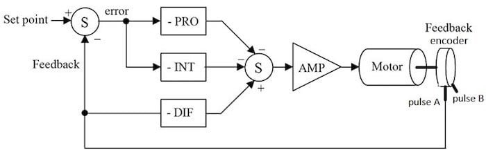
Figure 11. PID block diagram as a position controller
The error is multiplied by the gain of the proportional block. Notice that the block diagram shows this as a negative gain. This was done so that the block diagram and the schematic (presented later) will be consistent with each other. The proportional amplifier output is sent to the second summing junction, where the sign is again inverted. The amplifier is used to boost the output signal voltage, so it can be fed back to the GreenPAK to the PWM block to output a PWM signal that drives the motor through the motor driver.
Proportional Operation
Note: An error must be present!
The system will try to correct the error by turning the motor in a direction that opposes the error with appropriate speed.
The intensity of the correction is determined by proportional gain. If there is no error, there is no proportional drive.
Integral Operation
Integrating the error then provides a correction signal to the motor.
Note: An error must be present!
The integral section accumulates the error. A small error can become a large correction over time.
As the error is accumulated, the motor is forced to correct the error.
The integrator will overshoot the set-point. It must produce an error to counteract the input signal to discharge the capacitor.
Derivative Operation
When the motor starts to turn, the voltage measured by the resistor will be increasing or decreasing. If we have a voltage changing over a time, we have a ramp! The slope of this ramp changes with the speed of the motor. If the motor is moving quickly, the slope is high. Consequently, the output of the derivative stage will be high as well.
Note: The motor must be moving!
The differentiator will have a high output voltage when the motor is moving quickly and a low voltage when the motor is moving slowly.
This signal is applied in such a way as to slow down the motor.
If the motor is not moving, the differentiator has 0 output voltage.
The connections for the differentiator are different than the proportional and integral sections. The differentiator receives its input directly from the resistor. It, therefore, measures only the speed at which the motor is moving. It does not care about the set-point.
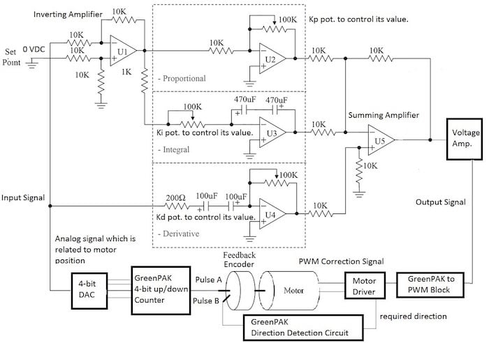
Figure 12. Schematic of analog PID controller circuit along with the other blocks of the system
PID Parameters and its Effects on the System Response
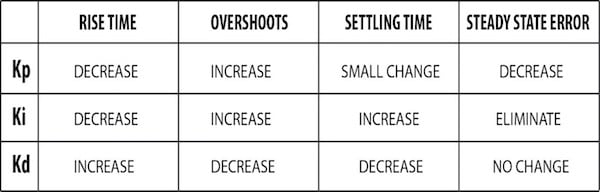
Figure 13. Increasing PID Parameters’ effect on the overall system response
Implementing the Circuit using SLG88104
I used a variable resistor to adjust the setpoint to the PID circuit. The setpoint is the initial value of the counter which is 127 i.e. I needed about 3.27 volts. The input of the variable resistor is the VDD of our SLG46621 and we adjust the output to 3.27 V using the variable resistor.
After testing the PID circuit above, I needed to make a voltage amplifier using another op-amp to amplify the output signal. This causes the change in voltage to be more noticeable.
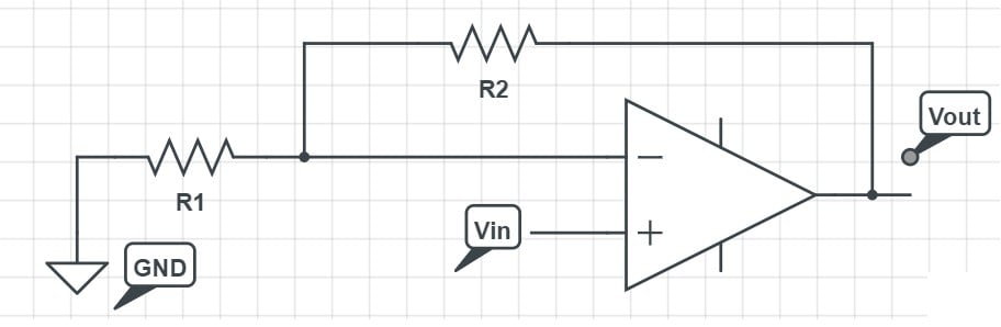
Figure 14. Non-inverting voltage amplifier
To overcome the issue of adding another op-amp to correct the sign of the op-amp I used a non-inverting amplifier configuration. The output voltage is given by:
I chose R1 to be 1 kΩ and R2 to be 10 kΩ so the voltage is amplified by 11 times from the original signal. The output signal will be changing from approximately 0 to 4.7 V.
Note that: if you aren't using an SLG88104, don't forget your +V and -V to the op-amp for appropriate operation like the one explained in the DAC operation.
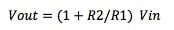
I made a PCB using EagleCAD software for the analog PID which accepts either the SLG88104 or a LM358 to compare between the output of both amplifiers. The PCB has test pins for the input signal, output signal before amplification and setpoint. Later, I added test pins through jumpers for the output signal after amplification.

Figure 15. Analog PID schematic using Eagle software before voltage amplification
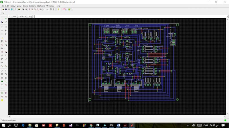
Figure 16. Analog PID circuit board using Eagle software before voltage amplification
Note, that if you want to use LM358 just put the IC using its holder in the PCB. If you want to use the SLG88104 connect the OpAmps from SLG88104 evaluation board to the pin headers' extension on the far left. The PCB is clearly labeled for easy connection and debugging.
The voltage amplification circuit is made separately in a small breadboard as you won’t need to amplify the voltage if you are using LM358 however, you will need so if you are using SLG88104.
SLG88104 vs LM358
Although you will need to add an extra op-amp to amplify the voltage when using the SLG88104 there are several key benefits with this op-amp; it is less noisy, has faster response to change in input signal than LM358, and is and noticeably smaller when compared to LM358, so this analog PID circuit can be redesigned using surface mount components to be more compact and still exhibit the same performance.
Taking the Analog Signal
The analog signal, which controls the PWM to the PWM block in GreenPAK and comes out from the PID circuit, is the correction signal that maintains the motor speed to reach the zero position which is at 127 count (initial value of the counter). Since this signal is analog it cannot be fed directly to the motor driver, we must first feed the GreenPAK to the PWM block. We then use the output PWM signal to maintain the motor speed.
I used the app note AN-1057 servo motor control as a reference to adjust the PWM block parameters.
Figure 17. Matrix0 connection for the PWM block
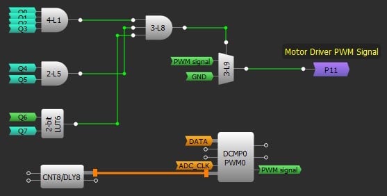
Figure 18. Matrix1 connection for the PWM block
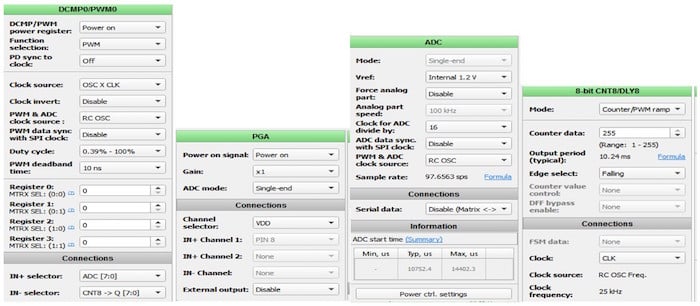
Figure 19. PWM circuit parameters
Note that, at the zero position which is our initial value 127 the motor will never stop; the oscillations may trigger a count up or down. Even if there is only a small voltage, the motor will keep oscillating around the zero position. I made a multiplexer to control the state of pin 5, which feeds the PWM signal to the motor driver. When the zero-position point occurs states Q0 to Q6 are HIGH and Q7 is LOW.
However, in any other cases, the pin 20 output will be connected to the output of the PWM block as a PWM signal fed to the motor driver. This ensures that the motor will have to stop at the zero position with some acceptable error. This is because I used the same blocks used to control the DC servo motor which needed a 1.5ms pulse at 0 degrees and this multiplexer trick ensured there is no output when the count is 127 i.e. zero position.
Choosing the Right Direction Pin to Connect to the Motor Driver
Now, let's revise our scenario: the motor starts initially at the zero position, if we move it clockwise it must move counter-clockwise to counteract the movement with the appropriate output speed from the PWM block to reach the zero position, or vice versa if moving counter-clockwise and that is what we actually get from DFF3 output. So, moving clockwise will output a LOW signal which is fed to the motor driver, so it makes the motor move counterclockwise to counteract the movement with the appropriate output speed from the PWM block and vice versa.
The motor driver PWM pin is connected to Pin 5 and the motor driver direction pin is connected to pin 6.
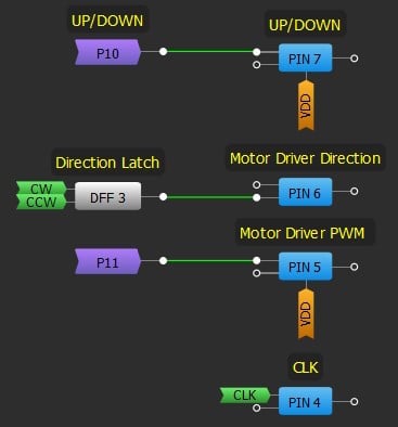
Figure 20. Motor drive pins
Final System Lookout and Resources Utilization
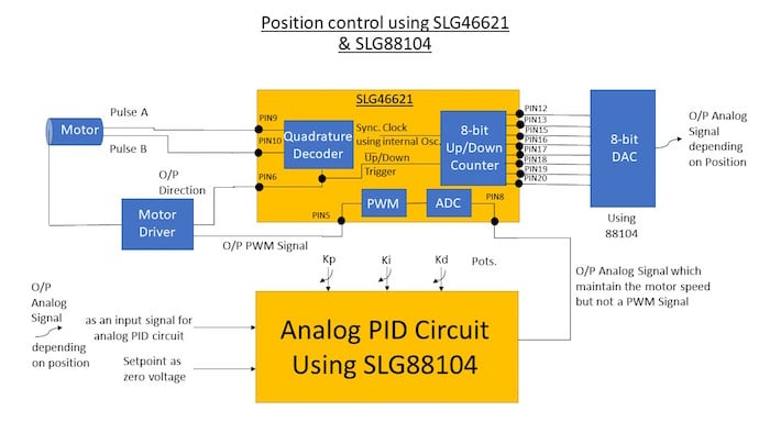
Figure 21. System block diagram of position control
How the System Works: A Summary
- The motor encoder output has two outputs: pulse A and pulse B, which are used for feeding the direction signal to the motor driver and the clocked quadrature circuit to trigger the counter up or down depending on the direction of the motor;
- An 8-bit up/down counter is used to count the slots the disk of the motor encoder covered: up in CW direction and down in CCW direction;
- This data will be converted to an analog signal using an external DAC, then it will be fed to the analog PID circuit and the setpoint will be set to the initial value of the counter which is 127;
- Adjust the system PID parameters until you get a stable response then the output of the PID should be a signal that maintains the motor speed. This output isn't a PWM signal, so it should be fed back to the GreenPAK;
- The analog signal will go through the ADC block then to the PWM block to output a corresponding PWM signal;
- Now we have the appropriate PWM signal and the direction signal from the direction detection circuit, which should be fed to the motor driver to correct the motor position.
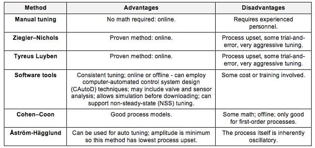
PID Parameters Tuning
PID tuning is a complicated process and within the scope of the app note.
For the scope of this application, which focuses on introducing students to the idea of PID control, trial and error is the perfect way to tune the PID parameters, since you watch the response of your system and tune the parameters to reach a stability point with no overshooting nor oscillations.
However, for small, low torque motors with little or no gearing, one procedure you can use to get a good baseline tune is to probe its response to a disturbance.
To tune a PID use the following steps:
- Set all gains to zero;
- Increase the P gain until the response to a disturbance is steady oscillation;
- Increase the D gain until the oscillations go away (i.e. it's critically damped);
- Repeat steps 2 and 3 until increasing the D gain does not stop the oscillations;
- Set P and D to the last stable values;
- Increase the I gain until it brings you to the setpoint with the number of oscillations desired (normally zero but a quicker response can be had if you don't mind a couple oscillations of overshoot).
What disturbance you use depends upon the mechanism attached to the controller. Normally, moving the mechanism by hand away from the setpoint and letting go is enough. If the oscillations grow bigger and bigger then you need to reduce the P gain.
If you set the D gain too high the system will begin to chatter (vibrate at a higher frequency than the P gain oscillations). If this happens, reduce the D gain until it stops.
Table 1. Comparison Between PID Tuning Methods
Modifying the System for Speed Control
The number of pulses per second is directly proportional to the speed of the motor. Pulse A is decoded to produce a count up pulse or a count down pulse. For decoding in software, the A output is read by software counters and counts per second are proportional to revolutions per second.
.jpg)
Figure 22. Decoding rotary encoder for speed control block diagram
System Block Diagram
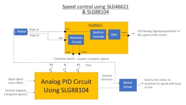
Figure 23. System block diagram of speed control
Arduino Realization
One alternative to using a GreenPAK to perform PID control is to use an Arduino, which is a popular microcontroller used by hobbyists. Compared to a GreenPAK, the Arduino solution requires some programming knowledge and significantly more space in the project since and Arduino is much larger than a GreenPAK. Additionally, a GreenPAK costs far less than the cheapest Arduino.
Also, as previously mentioned, a software-focused PID controller has limitations. Implementing PID in hardware gives the user control over every parameter in the design but can be more difficult to adjust.
#include #include double Setpoint, Input, Output; PID myPID(&Input, &Output, &Setpoint,1.002,0.0001,0.01, DIRECT); Encoder myEnc(2, 8); long oldPosition = -999; void setup() { Serial.begin(9600); pinMode(10,OUTPUT); pinMode(9,OUTPUT); Input = myEnc.read(); Setpoint = 0; myPID.SetMode(AUTOMATIC); myPID.SetOutputLimits(-254,254); myPID.SetSampleTime(60); } void loop() { long newPosition = myEnc.read(); if (newPosition != oldPosition) { oldPosition = newPosition; Input = myEnc.read(); myPID.Compute(); Serial.println(Output); Serial.println(newPosition); if(Output > 0){ digitalWrite(10,HIGH); analogWrite(9,abs(Output)); } else{ digitalWrite(10,LOW); analogWrite(9,abs(Output)); } } }Project Results
Each part of the system was implemented discretely, then the parts were integrated together and the whole system was debugged. The PCB design made it easy to debug the system because of the test pins.
Part 1: Position and Speed Control of a DC Motor using Analog PID Controller
Part 2: Position and Speed Control of a DC Motor using Analog PID Controller
The following tests have been applied while building the educational kit:
- Unit testing: I divided the application into small pieces and tested each small piece alone for correct operation
- GreenPAK up/down counter with scaling: the main idea is moving the pointer through the scaling and watch the counter increase through the scaling, I made an external circuit with 8 LEDs to test the 8-bit counter and another separate LED for direction detection i.e. ON while moving CCW and OFF while moving CW indicating the motor driver correct signal;
- DAC circuit: I verified that the DAC operated as described in section 4 of this app note;
- Analog PID circuit without amplification: before designing the PCB, I made the analog PID circuit using a breadboard and tested it through an analog signal given from an Arduino. Later, I tested it through the input signal from the 8-bit DAC;
- Analog PID circuit with amplification: I probed the PID output after the op-amp amplification;
- Motor driver: I tested the motor driver with input PWM and direction signals from both the Arduino and GreenPAK implementations.
- Integration testing: I attached small pieces of the system to each other and tested them as design blocks.
- System testing: I tested the whole system as a black box. I turned the kit on then checked the motor response with respect to the pointer movement.
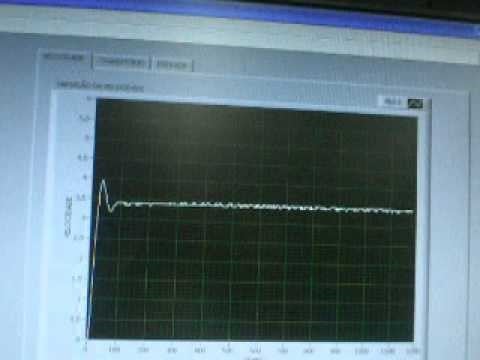
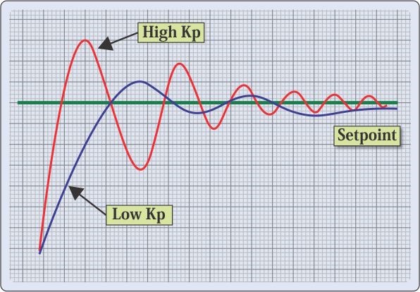
- Acceptance testing: reaching the perfect parameters for stable system and noticing how changing the potentiometer’s value affects the response. I used the below curves as a guide for perfect response.
Figure 24. Oscilloscope screenshot of the system reaching a stable system response
Figure 25. Reference curves for P and I parameters
Final Assemblies
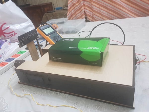
Figure 26. Final assembly of the system before putting it into the box
Figure 27. Final appearance of the educational kit
Conclusion
This app note demonstrates how to make a position and speed control of a DC motor. This can be used as an educational kit to show the effects of proportional, integral, and derivative control schemes as well as the effect of saturation, anti-windup, and controller update rate on stability, overshoot and steady state error.
Only a few internal blocks of SLG46621V are used, leaving the bulk of the blocks available to build other circuitry around it. This is an ideal example of a mixed signal IC as both analog and digital blocks are used in this application.
An LCD can be added later to display the PID parameter values.
GreenPAK implementation doesn't require any additional hardware or software development when compared to microcontrollers. Additionally, the focus on hardware-driven PID control ensures the fast response needed for the analog PID controller.
References
For related documents and software, please visit GreenPak's product page.
- GreenPAK Designer Software, Software Download and User Guide
- AN-CM-xxx Position and Speed Control of a DC Motor using Analog PID Controller, GreenPAK Design File (zip file)
- GreenPAK Development Tools
- GreenPAK Application Notes
Industry Articles are a form of content that allows industry partners to share useful news, messages, and technology with All About Circuits readers in a way editorial content is not well suited to. All Industry Articles are subject to strict editorial guidelines with the intention of offering readers useful news, technical expertise, or stories. The viewpoints and opinions expressed in Industry Articles are those of the partner and not necessarily those of All About Circuits or its writers.