Facebook
 Google
 GitHub
 Linkedin
New MOSFET Models To Simplify Your 3D Thermal Fluid Analysis Simulations
Learn how to use a simplified MOSFET model for CFD thermal analysis with step-by-step instructions and guidelines on how to interpret the simulation results.
One of the problems with power MOSFETs is the heat they generate causes serious performance issues. Such thermal issues impact the reliability of the MOSFET and the circuit dependent upon it. Unfortunately, attempts at developing MOSFET models for Computational Fluid Dynamics (CFD) thermal analysis can be complicated.
This article presents a simplified MOSFET model, as shown in Figure 1, for use in CFD thermal analysis simulations, examples of how to interpret the cooling simulation results, and step-by-step instructions for including them in simulations.
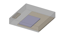
Figure 1. Simplified 3D MOSFET model for use in CFD thermal cooling analysis. Image used courtesy of Toshiba
Why Thermal Analysis is Important for MOSFETs
The heat generated by power MOSFETs can impact the entire circuit and, potentially, the functionality of devices dependent on that circuit. For example, thermal design guidelines exist for the placement of a power MOSFET in a chassis to minimize its heat effects.
Thermal analysis methods are broadly categorized into two techniques:
- A simplified model that converts heat-flow paths to an electric circuit network, which only considers 1D behavior in a SPICE simulation.
- A three-dimensional CFD model generated from device geometry that calculates the fluid's three-dimensional behavior, including temperature distribution and heat flow.
Review of CFD for Thermal Analysis
CFD is a combination of numerical methods, data structures, and fluid dynamics used to solve problems related to fluid flow. CFD is used extensively to perform complex thermal analyses, including those related to electronics' thermal analysis and management.
There are several benefits to the use of CFD for thermal analysis. For example, design modifications to the physical layout and components used are much cheaper to implement in a simulation than in a physical model. Depending on the skill of the CFD analyst, the results can be highly accurate and provide an enhanced understanding of thermal behavior and interactions. And CFD results can generate highly useful visualizations of temperature, heat flow, airflow, and more.
Because of the complex nature of components thermally interacting on a circuit, MOSFET thermal analysis CFD simulation involves three different forms of heat transfer:
- Conduction, through physical contact between components
- Convective, as fluids (typically air) move around the components
- Radiative, as some elements generate heat and others absorb it
Such complexity further illustrates the need for a simplified MOSFET model.
Simplified Model for MOSFET Thermal Analysis
The model in Figure 2 simplifies actual component shapes affecting the block-shaped structure's heat-flow path. Note that the model comprises a physical representation of individual components (mold, chip, solder, gate pins, and an exposed drain pad) and material properties for each element.
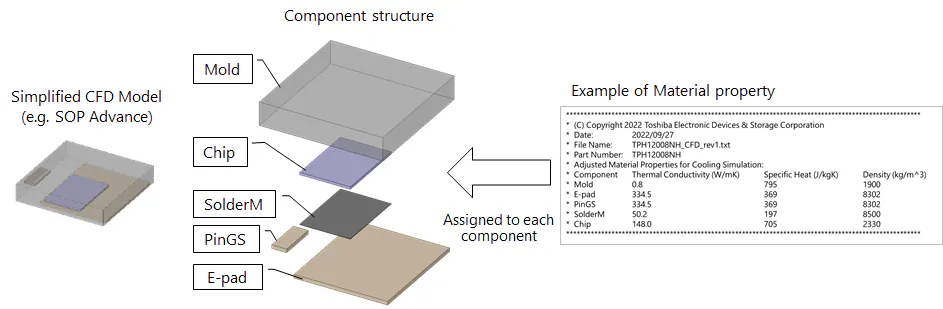
Figure 2. Components of the simplified 3D CFD model for a packaged power MOSFET. Image used courtesy of Toshiba
Here is what the various abbreviations in Figure 2 mean:
- Mold: Refers to the enclosure
- Chip: Semiconductor integrated circuit
- SolderM: Solder for mounting the semiconductor chip
- PinGS: Gate and source pin
- E-pad: Drain pad exposed at the bottom of the package
A CFD model requires material properties for each component. Figure 3 provides an example of a material property file that includes values for thermal conductivity, specific heat, and density for each element of the model.
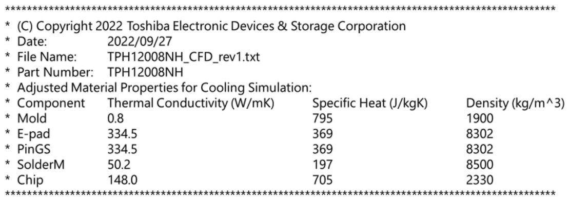
Figure 3. Example material property file. Image used courtesy of Toshiba
Example: Simplified 3D Thermal Fluid Analysis Cooling Simulation
This example illustrates the results obtained using the simplified MOSFET model, including surface temperature distribution, cross-sectional temperature distribution, heat flow, and flow velocity.
PCB System Layout
This cooling simulation example uses a printed circuit board (PCB) model with an inverter circuit. Figure 4 shows where the six MOSFETs are mounted on a PCB with a backside heatsink. The material properties shown previously in Figure 3 are used for the MOSFETs.
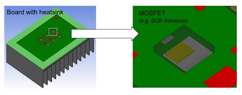
Figure 4. PCB with six MOSFETs for thermal simulation. Image used courtesy of Toshiba
Surface Temperature Distribution
Figure 5 shows the surface temperature distribution for the overall board, the mold surface of the upper right MOSFET, and the internal heat temperature distribution for the MOSFET.
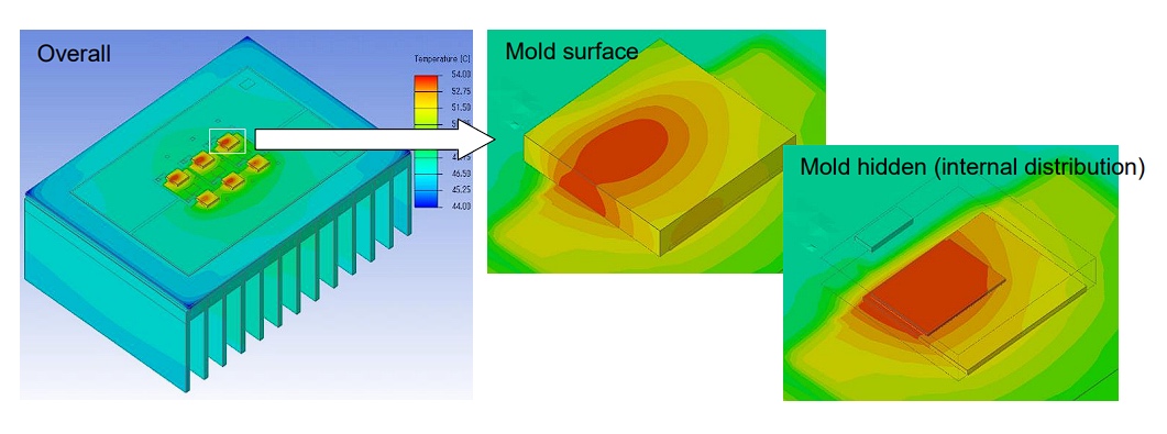
Figure 5. Surface temperature distribution. Image used courtesy of Toshiba
From Figure 5, the heat generated by the MOSFETs spreads to the board and heatsink. To better understand the temperature distribution within the MOSFET, the thermal fluid analysis tool allows the temperature within the device to be studied, even though it may not be visible in the actual set.
Figure 6 shows the temperature distribution inside the board, including the vias and copper (Cu) layers. In the image at right, the MOSFET is hidden from view to expose the PCB surface temperature distribution.
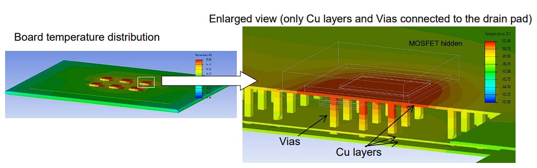
Figure 6. Temperature distribution inside the board. Image used courtesy of Toshiba
In this instance, we are looking at the MOSFET located at the far right in the image. Note the effects of the neighboring MOSFETs and the change in temperature distribution where there are no neighboring MOSFETs; also note that the temperatures are lower when further away from the MOSFETs, which aids in confirming the validity of the simplified MOSFET model.
Cross-Sectional Temperature Distribution
Figure 7 (right) shows the 2D cross-sectional temperature distribution of the heat sink, taken from the middle. First, note that the temperatures are highest towards the center of the heat sink where the MOSFETs are located. This result helps to confirm that the simplified MOSFET model is behaving as expected.
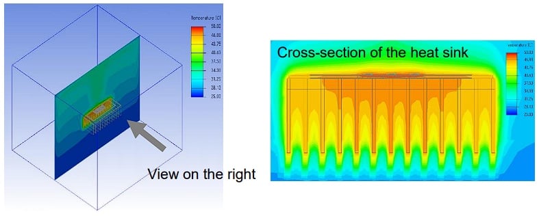
Figure 7. Cross-sectional temperature distribution. Image used courtesy of Toshiba
This view aids in checking the amount of heat being dissipated by the heatsink and the spread of the heat. As expected, the lowest temperatures are far from the heatsink and its components. The lowest temperatures on the heatsink are at the fins farthest away from the MOSFETs.
Flow Velocity and Heat Flow
Finally, Figure 8 illustrates the fluid display around the board in the simulation chamber set during analysis. This figure includes the airflow velocity distribution in the left image and the heat flow path in the right image.
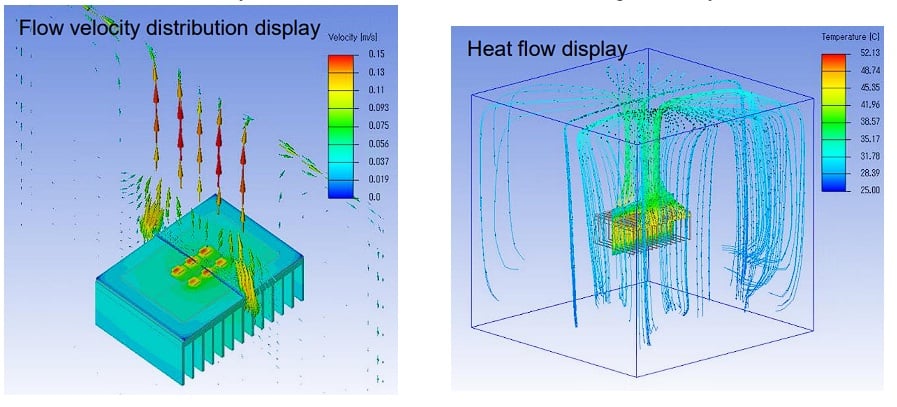
Figure 8. Airflow velocity and heat flow. Image used courtesy of Toshiba
Applying the Simplified CFD MOSFET Model
The model described in this article is simple to implement. The main page for the models is located at Simplified CFD MOSFET Model, with a list of Toshiba MOSFETs available with a simplified CFD model. The download for each MOSFET comes in the form of a compressed file that contains:
- The material property text (.txt) file with the thermal conductivity, specific heat, and density for the MOSFET, an example of which is shown in Figure 9.
- The STEP (*.stp) file containing the simplified 3D model of the MOSFET.
These files will enable you to use the simplified 3D MOSFET models in your simulations.
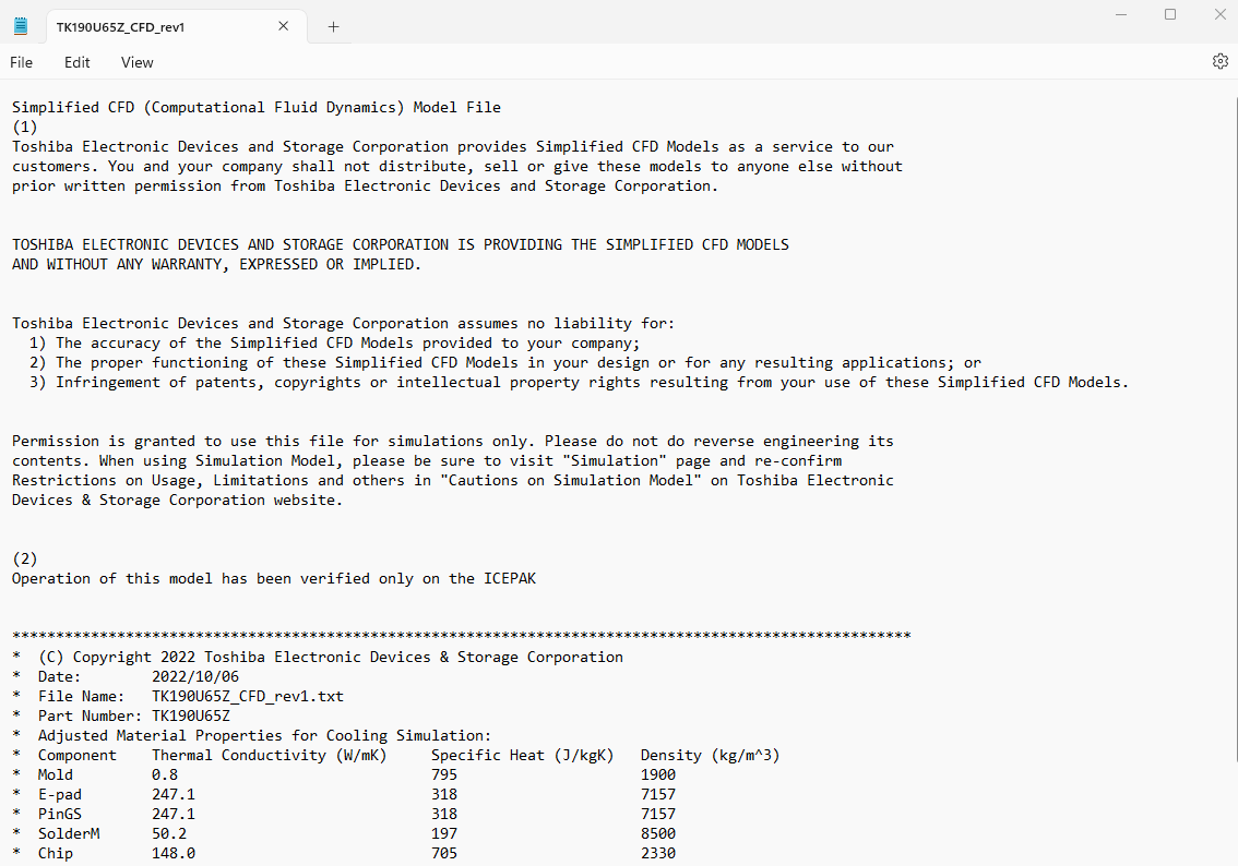
Figure 9. Typical contents of a material property text file. Image used courtesy of Toshiba
The steps for including the MOSFET(s) in a CFD simulation are:
- Download the compressed file for the desired MOSFET and extract it to any folder
- Convert the Simplified CFD Model to a simulation model with the 3D CAD tool used for thermal analysis
- Import the simulation model to the thermal fluid analysis tool
- Assign the physical property values described in the material property text file to each component of the imported model
- Run the cooling simulation
Getting Started with Simplified MOSFET Thermal Simulations
Including MOSFETs in thermal analysis cooling simulations is important but often complicated by the complexity of the MOSFET models. This article introduced a simplified model of MOSFETs that can be included in thermal CFD analysis of electronic boards. All that is required is the 3D model of the MOSFET in the form of a STEP file and the material properties of the MOSFET, both of which can be downloaded from Toshiba for hundreds of MOSFETs.
To learn more about how Toshiba MOSFETs can empower your simulations and your designs, contact Toshiba Electronic Devices & Storage Corporation.