 Facebook
 Google
 GitHub
 Linkedin
Rotary Controls For Modern Hardware Interfaces
From mechanical latches and liquid flow restrictors to the earliest radio tuners and volume adjusters, rotary controls have been a mainstay of effective interface design. Learn more about rotary controls for modern hardware interfaces.
From mechanical latches and liquid flow restrictors to the earliest radio tuners and volume adjusters, rotary controls have been a mainstay of effective interface design.
They offer precise tactile adjustment in a relatively small footprint with built-in visual feedback. High-resolution touch displays often mimic their mechanical counterparts by offering graphical rotary sliders, as shown in Figure 1.

Figure 1: UI rotary design element. Image used courtesy of Shutterstock
These sliders offer the same compact footprint and visual feedback as mechanical rotaries, but require an expensive display and lack the associated tactile benefits.
In most modern applications, a high-resolution color touch display is likely impractical and often even impossible. The designer must therefore resort to mechanical shafts and knobs, or attempt to achieve the same functionality with buttons or other simpler controls.
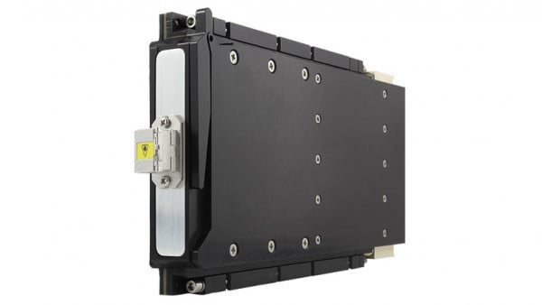
A recent example of a thin interface panel is shown in Figure 2, where three rotary controls are integrated with a variety of pushbuttons, indicators, and displays.

Figure 2: Modern thin user interface panel. Image used courtesy of ALMAX
Achieving an attractive and functional interface under these constraints is a difficult challenge, and requires the designer to dig deep into their tool chest and cleverly employ a wide variety of control options. This article discusses rotary control advancements and considerations for modern hardware interfaces and how relatively new technology - the MaxRotor - bridges the gaps in the current shortcomings of many potentiometers and encoders.
Designing A Hardware User Interface
For the sake of this discussion, consider an imaginary product as shown below in Figure 3, requiring an interface that includes an LCD screen with contrast control and a keypad for data entry and function selection.
The interface specifications require that it not be any thicker than 6 mm to accommodate the electromechanics mounted behind it within an industry-standard enclosure.

Figure 3: Imaginary product user interface. Image used courtesy of ALMAX
As a starting point to drive the thickness envelope, a keypad and function buttons can be implemented easily using a standard off-the-shelf or fully customized membrane solution.
As shown in Figure 4, these types of keypads are easily interfaced with common microcontrollers and are available in thicknesses of approximately 2 mm or less. A variety of panel mounting options are available including many that are tightly sealed and IP rated.

Figure 4: Off-the-shelf membrane keypad. Image used courtesy of Digikey
When considering the visual screen, the universe of display options has also grown in recent years to offer solutions of any shape and size ranging from e-ink and organic light-emitting diode (OLED) to thin-film transistor (TFT) and basic liquid crystal display (LCD).
An inexpensive matrix LCD display is shown as an example in Figure 5 and includes a built-in backlight with contrast control.

Figure 5: LCD (left) and contrast control circuit (right). Images used courtesy of Instructables and Farnell
This type of display is also rather thin at only 2 mm and fits nicely within the constraints of the product requirement while keeping costs at a minimum.
The dedicated contrast control circuit requires delivering an analog voltage to the V0 pin within the supply range of the display circuitry. This contrast control actually turns out to be one of the more complicated challenges of the entire interface design.
Rotary Control Options
As a starting point, one might consider the venerable potentiometer shown below in Figure 6.
Electrically, this could be wired simply across the power supply rails to create a voltage divider.
Additionally, the center tap output could be used to drive V0 and a large value, 100 kOhms for example, would minimize power consumption and complexity.

Figure 6: Standard panel mount potentiometer. Image used courtesy of Digikey
Mechanically, the situation is significantly more problematic.
Challenge of Using Pontentimeters
Potentiometers suffer from failure of the wipers and circuit components, typically only lasting 25-50k rotations.
In addition, the knob must be secured to the panel with a nut and lock washer, and a detent must be integrated to prevent the entire structure from rotating out of alignment.
What’s worse is that the body depth of most potentiometers greatly exceeds the available space, with many in the range of 9–10 mm. These characteristics in aggregate can make the potentiometer a relatively undesirable option.
Quadrature Encoders as a Rotary Solution
To achieve smaller body depth and simplify mounting requirements, another common rotary control worth considering is the quadrature encoder.
As shown in Figure 7, these encoders are available in both PCB and panel mount options very similar in nature to the potentiometer.

Figure 7: Traditional quadrature encoder and resulting signals. Image used courtesy of TTElectronics
Electrically, however, quadrature encoders introduce a whole new set of complications.
The output is typically two pulse trains that represent a particular amount of rotational travel and whose relative position can be used to ascertain rotational direction.
In order to use this for voltage control, as in the LCD contrast example above, an intermediate circuit must be used to convert the pulse train into an analog voltage.
Such a circuit is by no means simple and introduces an additional layer of complexity and cost.
Lastly, it is worth noting that the rotating pieces, electrical contacts, seals, and through-hole pins of a quadrature encoder are all encapsulated between the knob and the host PCB. This prevents the host PCB from sitting flush to the interface panel enclosure, a problem for capacitive touch sensors, buttons, and LED indicators.
The Benefits of MaxRotors
To bridge the gaps in the aforementioned shortcomings of potentiometers and encoders, relatively new technology has taken center stage: the MaxRotor.
As shown in the assembly diagram in Figure 8, the MaxRotor consists of a sandwich of mechanical parts on either side of a rigid or flexible circuit layer.
On the front side, a shaft, cover, and magnets are used with an optional detent ring to capture rotary motion from the user. As the magnets move across the top of the circuit layer, they pull with them a group of conductive metal balls that comprise the electrical armature on the backside of the circuit layer.

Figure 8: MaxRotor assembly. Image used courtesy of ALMAX
The result of this unique assembly is a highly configurable, highly reliable rotary control that can offer the industry’s thinnest overall depth.
From the top surface of the rotor to the bottom, the face is a mere 5.48 mm, all within a footprint of 25 mm x 25 mm.
After extensive testing to several hundred-thousand rotations, the MaxRotor is rated at 100,000 rotations, almost double the reliability of traditional encoders and potentiometers.
The extended life of the MaxRotor is actually provided by the use of a state-of-the-art gold-plated chrome steel ball contact system. The gold-plated chrome steel balls free-roll along the surface of the circuit contacts, which greatly minimize wear on the circuit, and there is no heat build-up.
The rotor comparison in the figure below shows the extreme thickness difference of a variety of mechanical rotors versus the minimal overall height of the MaxRotor, depicted on the far right in Figure 9.

Figure 9: MaxRotor (far right) panel depth compared to the competition. Image used courtesy of ALMAX
The circuit layer can be built into an off-the-shelf MaxRotor, or it can be fully customized in the end application as part of a larger PCB or Flex circuit.
A few examples are shown in Figure 10.

Figure 10: Examples of MaxRotor circuit options. Image used courtesy of ALMAX
For the aforementioned LCD contrast control circuit, a simple analog circuit (far right) can be used to provide the exact same functionality as a potentiometer.
The MaxRotor itself can be customized on the circuit layer and the mechanical layer to include a variety of features ranging from push buttons and quadrature output to rotational stops and tactile detents.
In the case of an LCD contrast nob, a very simple design can be realized by creating a dedicated circuit layer and constructing a “stand-alone” MaxRotor as shown in Figure 11.

Figure 11: MaxRotor implemented as a standalone device. Image used courtesy of ALMAX
This standalone configuration allows the MaxRotor to be easily installed alongside the keypad without integrating it into the same circuit board.
Figure 12, down below depicts the final implementation of the contrast knob and is a testament to the simplicity and capability of the MaxRotor.

Figure 12: MaxRotor contrasts control implementation. Image used courtesy of ALMAX
Utilizing a MaxRotor as a Rotary Solution
At first glance, the proposed user interface design might have appeared to be constrained by the complexity of a keypad or LCD, when in fact, the basic function of rotary contrast control introduces the toughest mechanical challenges.
By using a few off-the-shelf components and a highly configurable MaxRotor, the interface can in fact be realized in a thickness less than 6 mm with minimal design complexity and high reliability.
In general, the MaxRotor provides engineering solutions to challenges and limitations that have plagued companies in their efforts to provide highly reliable rotary controls. Some examples of these solutions include:
- Extended product life through the use of engineering plastics for the molded components, high-quality metal components, and the use of a state-of-the-art gold plated chrome steel ball contact system.
- Thin panel integrated design inherently eliminates the need for a complex wire harness or the associated electrical circuitry and power consumption of mechanical rotors.
- The engineering design focused on providing a rotor with simple integration with other technologies, and successfully minimized the penetrating overall thickness of the rotor package.
As user interface panels continue to advance in their shape and complexity, the MaxRotor can be the next staple in every designer’s toolbox.
Interested in the MaxRotor solution? Learn more at ALMAX’s website.
Related Content


Is Vldc in Fig 5 “correct”
it seems it should either be the voltage from ground to Vcc or form gnd to Vo
Wow, the whole point of the article seems to be to extol the virtues of physical controls vs. display controls because of tactile feedback, which is great and very lacking in modern display controls. Then throw in one of those cheesy membrane keyboards with crappy tactile feedback that after a while you can’t even tell if you engaged it or not, that end up with the top layer worn off of the most used membrane switch? Sinful. You instantly destroyed your cred. The worst possible switch to illustrate your point. Tactile feedback decay. Take a look at a well used gas pump membrane keyboard sometime.