Facebook
 Google
 GitHub
 Linkedin
Six Steps for Designing a Custom 3D Printed Electronics Enclosure
Rich resources are available today for crafting an enclosure using 3D printing. But where to begin? In this article, learn—step by step—how to design your own custom 3D printed electronics enclosure.
Whether you're an electronics engineer working at a hardware startup or an established enterprise—or simply a hobbyist working on your own electronics projects, chances are that you may have come across this situation: You need a custom-designed enclosure that perfectly matches your project’s requirements.
Hiring an industrial design firm to design a custom, market-ready enclosure may not be an option yet. Therefore, in this article, we focus on the best practices and design process to design your own custom 3D printed electronics enclosure. A beginner level proficiency in 3D CAD software is required to follow through.
Customized Versus Custom Enclosures
To start with, let’s differentiate between customized and custom enclosures because the terms are sometimes used interchangeably:-
Customized Enclosures
These are off-the-shelf enclosures that the manufacturer has already designed and/or produced. The manufacturer offers customizations by performing secondary operations according to your requirements like drilling holes, creating cut-outs for buttons or ports, adding graphics or logos, and so on.
The overall form and shape—especially for plastic enclosures—stays the same as what the manufacturer originally designed. Customized enclosures are a cost-effective option if you don’t require a completely tailor-made solution where you can differentiate with design.
Custom Enclosures
These enclosures are designed and manufactured from scratch, tailored to your specific requirements. A custom enclosure can be something that you design and 3D print yourself from scratch with minimal costs.
But if you need a professional, marketable design that can be mass-produced at scale, then you need the services of design and engineering professionals. The NRE (Non-Recurring Engineering Costs) to design and develop the enclosure, and the costs to set up injection molding tooling, easily runs into tens of thousands of dollars or more.
Steps for Designing Your Custom Enclosure for 3D Printing
Let’s take the example of a Raspberry Pi 5 board. Here, we’ll go through the step by step process of designing a custom enclosure. We’ll design a simple enclosure that is optimized for 3D printing. Other manufacturing processes, like injection molding have different, more stringent enclosure design guidelines.
Step 1: Model the PCB and Internal Components
Start by creating a 3D model of all the internal components and the PCB that will be housed in the enclosure (Figure 1). Usually manufacturers have downloadable 3D files and drawings for their components. Creating the 3D model of the internal components makes it easier to design the right-sized enclosure and check for any physical interferences later.
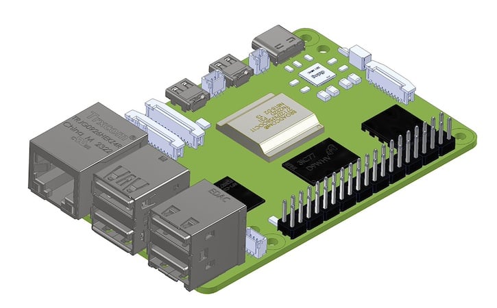
Figure 1. 3D model of a Raspberry Pi 5 board
Step 2: Model the Enclosure Shell
Create a solid body around the PCB, in the shape you desire your enclosure to be and create a shell from that solid body (Figure 2). Most 3D CAD software have a ‘shell’ or similar command that hollows out a solid body.
A wall thickness between 2 mm to 2.5 mm is common for plastic enclosures. Allow a clearance of at least 0.5 mm between each edge of the PCB and the enclosure walls and account for any wiring that may have to be routed within the enclosure. Not accounting for the space required by wires is a common mistake when designing enclosures that leads to improper fit later during prototyping.
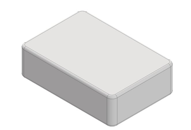
Figure 2. 3D model of the enclosure shell
Step 3: Create Cut-Outs and Separate the Casing Shell
Plan out where the parting line would be, this is where the two halves of the enclosure meet. For simple enclosures, this is usually a straight line in the middle. Create cut-outs for the various ports, buttons, lights or other features and split the enclosure shell along the parting line to create two halves (Figure 3).

Figure 3. Enclosure shell with parting lines for the two halves, along with the cut-outs for ports, buttons, etc.
Step 4: Create Mounting and Fastening Features
An embossed feature, or a feature raised above the surface called “boss” is used to assist in assembly, serve as a receptacle for screw or threaded inserts, or for alignment. In our example, we use four bosses that will help in the assembly of the enclosure halves as well as the PCB (Figure 4).
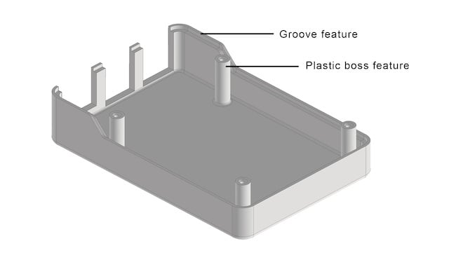
Figure 4. Bottom half of the enclosure with four “bosses” for screw threads. Groove feature helps align the top and bottom halves.
We use self-tapping screws that will “bite” into the plastic boss and keep the assembly held together in place. Screw manufacturers have guidelines on appropriate pilot hole dimensions for specific screw sizes that will allow optimal assembly. It is a quick and simple fastening method, but if your enclosure requires frequent assembly/disassembly or high pull-out strength, then you may consider using threaded inserts or a captive nut embedded into the enclosure.
Another feature that helps in the assembly and alignment of enclosure halves is the lip and groove feature. One enclosure half has a lip that sits into the other half that has a groove. Like other parts, there should also be appropriate clearance given between the lip and groove to prevent interference.
Step 5: Create Support Features
Ribs and gussets add strength to the enclosure without increasing the wall thickness (Figure 5). For injection molding, the ribs and gussets are usually 50% to 60% of the wall thickness, but for 3D printing there is no such limitation. A thickness of less than 0.8 mm is not recommended.
In our example, we add supporting features to the bosses and to the thin-walled sections near the cut-outs in the top half of the enclosure.
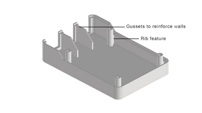
Figure 5. Ribs and gussets add strength to the enclosure.
Step 6: Additional Features
Based on your enclosure requirements, there may be a need to add some additional features like cooling vents, enclosure mounting features, attachment points and such. In our example, we’ve added cooling vents on the top enclosure half (Figure 6) along with our logo, and adhesive rubber feet on the bottom enclosure half (Figure 7).
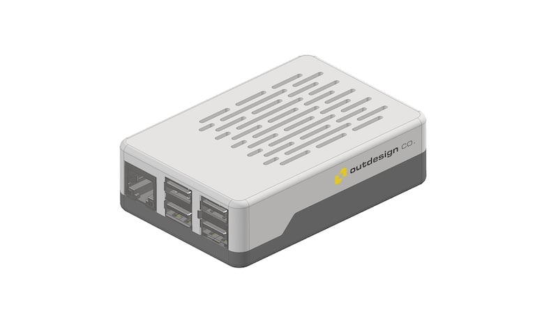
Figure 6. Shown here, we’ve added cooling vents on the top enclosure half.
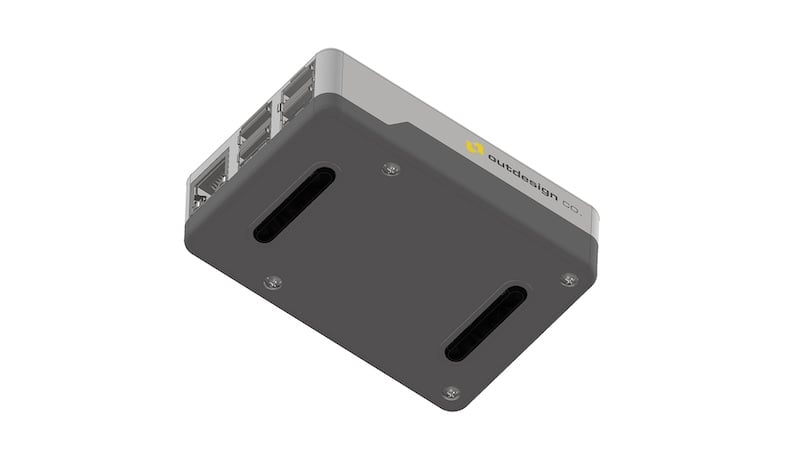
Figure 7. Adhesive rubber feet have been added to the bottom enclosure half.
To summarize, as 3D printing has become more accessible in recent times, along with free 3D CAD software, it’s now possible for electronics engineers and hobbyists to create their own custom 3D printed enclosures for their projects. They no longer need to rely on off-the-shelf or customized options that don’t perfectly fit their project’s requirements.
An engineer who has their own 3D printer and is fairly proficient in using 3D CAD software, can design and 3D print a custom enclosure in less time than it would take to have an off-the-shelf enclosure shipped to them!
All images used courtesy of Outdesign