 Facebook
 Google
 GitHub
 Linkedin
Why CAD Models are Failing Professional Electrical Engineers
In this article, Octopart's Director of Operations for Part Data Geof Lipman explores how traditional CAD modeling needs to change in order for electrical engineers to keep up with product design deadlines.
When we look back on the early 21st century, what the date will be when professional electrical engineers stopped building their own ECAD models. Not 2020, but the path to this future is becoming clearer than some might think.
Recent History of CAD Modeling
In 2000, electrical engineers (EEs) made their own ECAD models by reading datasheets, making BOMs, and perusing vendors on the internet. When the time came to build the board, EEs generated Gerber files and sent those files and the BOM spreadsheet to an electronic manufacturing services (EMS) company. The engineer’s job got easier as EDA tools got more sophisticated. BOM management and then part search became integrated into EDA tools, streamlining the process. Nowadays, engineers can search for parts and check the price, availability, specs, and other important information all in real-time without leaving the EDA screen.
What Comes Next?
That’s a great start, but it’s just the beginning of what engineers need to have a more integrated workflow for PCBA design. Next on the horizon will be more productivity features like trusted, quality ECAD models.
The Landscape: Demands on Electrical Engineers
Currently, product design cycles are short — and getting shorter. Today, the first company to get a design to market has a huge advantage. This means that design engineers are increasingly under pressure to reduce design times. The industry has responded by providing libraries of ECAD models, either for free or for purchase, with the promise that these models could be dropped directly into new designs, saving time and effort.
However, although there are an impressive number of ECAD models available if you believe the marketing pitches, any real-world design will find the engineer scrambling to find models and often coming up short.
Problems within these ECAD models are prolific:
- The symbol can be generic or nonsensical
- There is no 3D model
- The 3D model is a simple box instead of a proper representation
- The footprint has poorly constructed slots
- There are solder mask violations
The list of problems with readily available models is nearly endless. In the end, the time spent chasing down and troubleshooting ECAD models can sometimes be longer than simply creating them yourself. So where’s the time saved there?
Current Day Realities: Testing the ECAD Market
I wanted to find out for myself if currently available ECAD could improve my productivity, or at least reduce some of the more tedious aspects of board design. I found three publicly available BOMs and evaluated the quantity and quality of models for them.
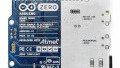
Arduino Micro
The first I tried was Arduino Micro. Of the 22 parts on this BOM, I could only find 14 or 63% that had complete CAD coverage that I could download. So that helps, but I still need to build my own CAD for 37% of the parts.
Replicape: A RepRap 3D Printer Controller
With Replicape, of the 22 non-passive parts on this BOM, I could only find 11, or 50%, that had complete CAD coverage that I could download.
openHPSDR: A High-Performance Open SRD Receiver
Using openHPSDR, of the 40 non-passive parts on this BOM, I could only find 27 or 68% that had complete CAD coverage that I could download.
ECAD Market Test Results
Part Coverage
Most sources have decent models for basic 2 terminal passive SMD components. Of course, making passive components is the quickest ECAD task, so my numbers are focussed on non-passive parts. ECAD coverage for non-passive parts ranges from 50% to 68%. That’s not terrible, but I still would have to build a bunch of models myself. Assuming that the model quality is high, this could save me some time.
Symbol Quality
Symbol quality is all over the map. A lot of these models are definitely not acceptable for professional work. Issues I discovered include a resistor that is drawn as a box with both pins on the same side and a transistor that is drawn as a box with pins on left and right. These symbols might meet the minimum requirements of having the right number of pins, but if I were to present a schematic with some of these symbols on my schematic to a paying customer, or to my engineering manager, I would get sent back to the drawing board. So that doesn’t save me any time because I have to redraw a lot of these symbols myself.

Figure 1. Unclear schematic symbols.

Figure 2. My redrawn symbols.
Footprint Quality
At first glance, footprints seem like they are better quality than the symbols. However, the requirements for footprints are more challenging than symbols. Small deviations on the footprint can cause Design for Manufacturing (DFM) issues that cost real money. And many of these parts are marked as “community-verified.” What should I do with that? Professional ethics require that I pull out the datasheet and check all the dimensions of the part to make sure that it is going to work. Sending a PCB design to fab is too high stakes to just trust that somebody on the internet did the due diligence and should be trusted without oversight. In the end, having to check every footprint takes less time than building something from scratch, but not a lot less.

Figure 3. Do you trust this solder mask pattern?

Figure 4. Datasheet confirms the Figure 3 footprint is correct.
3D Models
3D models are the “most often omitted” models for the parts I looked at. Stylistically, there were color and “realistic-ness” variations from provider to provider, but where the model exists and is accurate, it is helpful to have. It’s possible to build PCBAs without 3D models, but these days an EE is expected to produce results that can be handed to Industrial Design and Mechanical Engineering colleagues to build the enclosures, check fit, and in some cases produce marketing images. I’m confident in asserting that for most of the ID/ME concerns, the 3D models I found are useful. But if you need photorealistic renders for some reason, you’ll need to put in a lot of extra work.

Figure 5. An unclear 3D model.

Figure 6. A clear, concise 3D model.
Final Verdict
Although there are a number of companies that promise high-quality ECAD models in high quantities in their marketing materials, the truth seems less sanguine. Although using free, downloadable ECAD might result in some moderate time savings, professional engineers that have money and careers on the line cannot trust the majority of free downloadable ECAD models. That, coupled with the time spent searching four or five different sites to check for available models, means that “drag and drop” ECAD is still a thing of the future.
One Engineer’s Way Forward
So given that we still don’t have jet packs or professional quality, free ECAD models what is the path forward? It seems simple and obvious, but probably it’s worth saying what working engineers already know.
Symbols have to be high quality. Schematic diagrams exist to transmit understanding, and so engineers have devised symbols that have been in use for like 100 years to convey this understanding. ECAD symbols need to comply with this tradition, and with sensible standards in the field.
Footprints should follow the manufacturer’s recommendations. For standard package type parts, IPC footprints should also be provided. The biggest challenge here is confidence: when money, time, and jobs are on the line, what will make engineers trust footprints?
3D models should follow a simple rule. They should look like and be the same size as an actual part. And the best 3D part is “photorealistic,” or at least has the right colors and shapes.
Octopart is working on solving these problems by making ECAD that is built and verified by actual electrical engineers. We build continuously, so our library has more models every day. Every part we build has a schematic symbol, PCB footprint, and 3D model. Every schematic symbol looks like it should, following the guidelines of IEEE 315-1975 and IEC 60617. We provide footprints that follow the manufacturer’s guidelines, and when standard packages are used, we also supply three IPC-7351 compliant footprints for different PCB densities. And every part has a high-quality 3D model. Every part is checked three times by actual electrical engineers before it is released as a “Verified” model.
Getting to the ideal future where EEs can stop building ECAD models and rely on free, high-quality, and accurate resources from readily available libraries might be years off, but we’re well on the way to achieving that reality by acknowledging the gaps we currently have in our systems, establishing sensible guidelines for future model creation, and setting the bar higher for future work.


Great article! It definitely capture the daily-basis issues we’ve to deal with. I often build my footprints from scratch, even for passive components!
The might be correct if you are an electronic design engineer. If you are an electrical engineer, you will probably be using EPlan (like my self) or be using AutoCAD Electrical. I can only speak for EPlan, they have a full library of electrical components and the CAD can produce accurate panel layouts in 2D or 3D as well as a BOM list with terminal layouts.
Fair point, Ash. I could have been more specific about the job title. And yes, we think that this is mainly a problem in the electronic/PCBA design space, regardless of title. Thanks.