 Facebook
 Google
 GitHub
 Linkedin
Adjustable Linear Constant-Current Control: An LED Controller from Diodes Incorporated
Diodes Incorporated announces two new adjustable constant-current LED controllers that accept input voltages ranging from 4.5V to 60V.
Diodes Incorporated announces two new adjustable constant-current LED controllers that accept input voltages ranging from 4.5V to 60V.
Diodes Inc. recently announced the AL5815 and AL5816, which are two new LED controllers that offer a wide input voltage range (from 4.5V to 60V), are capable of driving either external BJTs or external MOSFETs, and have linear PWM-based dimming capabilities.
Figure 1. The AL5815 and AL5816, from Diodes Inc., are both capable of driving BJTs or MOSFETs. These typical application circuits are from the AL5815/16 datasheet (PDF).
Pin 1: ENB vs. PWM
The AL5815 and AL5816 share the same datasheet and are both available (only) in 5-pin SOT25 packages; they differ only with respect to the functionality of Pin 1.
Pin 1 of the AL5815 is labeled ENB (for "enable"). This serves as an active-low enable feature which has a built-in soft-start delay, used to prevent high-current surges at startup.
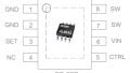
This pin also, however, allows for limited LED dimming capabilities. I say limited because, as is clearly stated in the datasheet, the dimming feature can be adjusted only by applying a low (less than 200Hz) PWM frequency (this limitation is due to the IC's soft-start feature). If a higher PWM frequency is required, then the AL5816 IC must be used, since its pin 1—labeled PWM—can operate at frequencies greater than 200Hz. The figure below shows the pinouts of these two ICs.

Figure 2. The difference between the AL5815 and AL5816 is the functionality of pin 1: enable vs. PWM. Diagram taken from the AL5815/16 datasheet (PDF).
A Wide Operating Temperature Range... But Perhaps Not as Wide as It Might Seem
While it's true that the operating ambient temperature range is listed as -40°C to +125°C and the operating junction temperature range is -40°C to +150°C, be mindful that these temperature specs are listed as the absolute maximum ratings.
Furthermore, be aware of Note 4, which states, "These are stress ratings only, and functional operation of the device at conditions between maximum recommended operating conditions and absolute maximum ratings is not implied."
The recommended operating conditions state the following temperature specs:
- Operating ambient temperature: -40°C to +105°C
- Operating junction temperature: -40°C to +125°C
I personally haven't seen too many other datasheets call out different ambient and junction temperature range values for the absolute maximum and the recommended maximum specs.

Figure 3. The operating ambient and junction temperature specs have both absolute maximum values and recommended maximum values. Taken from the AL5815/16 datasheet (PDF).
Seemingly Excellent Temperature Stability
As stated in the AL5815/16 New Product Announcement, these ICs seemingly offer excellent temperature stability. And based on some of the temperature performance characteristics (see image below), these ICs do indeed show a first-rate temperature stability.

Figure 4. The temperature plots show the IC’s excellent temperature stability characteristics, as advertised. Images taken from the AL5815/16 datasheet (PDF).
Very Linear LED PWM Dimming Characteristics
If you're looking for a very linear LED dimming controller — that is, linearity of the LED current (as a percent) vs. the PWM duty cycle—then you might want to consider using one of these two ICs. The two plots below depict actual vs. ideal linear dimming curves for both the AL5815 and AL5816. And, as can be observed, both ICs seem to have impressively linear characteristics... at least under the stated testing parameters (i.e., VIN, LED current, number of LEDs).

Figure 5. Both ICs show excellent linear dimming characteristics, at least for the stated operating conditions. Plots taken from the AL5815/16 datasheet (PDF).
Output Current Drive
When using a string of LEDs, the LEDs' desired regulated current appears to be quite simple to calculate.

Figure 6. The value of RS determines the amount of current through the LED string. Diagrams taken from the AL5815/16 datasheet (PDF).
Simply choose an appropriate resistor (RS) based on the following output current equation:
$$I_{LED} = \frac{V_{FB}}{R_S}$$
where ILED is the current through the LED, VFB is the voltage at the FB pin (200mV), and RS is the value of the sense resistor.
And don't forget to properly size (in terms of power) the chosen resistor:
$$P = V_{SENSE} * I_{LED}$$
where P is the power dissipated by the resistor, VSENSE is 200mV, and ILED is the desired current through the LED string.
Additionally, the same current through more than one string of LEDs can be set, as stated in the datasheet, by using matched BJTs/MOSFETs and RS resistors (see image below).

Figure 7. Two or more LED strings can operate in parallel, from the AL5815/16 datasheet (PDF). If the same ILED is desired, be sure to use matched Q1/Q2 and RS1/RS2 components.
Have you had a chance to use either of these new 60V LED dimmable controllers? If so, leave a comment and tell us about your experiences.
Related Content


what BJT can I use? 2N3904?