 Facebook
 Google
 GitHub
 Linkedin
A Simple Method of Driving Low-Current LED Strips: Current Regulators from Diodes Incorporated
Diodes Incorporated has released two new constant-current regulators for powering and dimming low-current LED strips.
Diodes Incorporated has released two new constant-current regulators for powering and dimming low-current LED strips.
Diodes Inc. recently released the BCR420U and BCR421U constant-current regulators (CCRs) for powering LEDs and LED strips. The BCR420U is capable of regulating currents from 10 mA to 200 mA; the BCR421U supports nearly twice as much current (up to 350 mA) and can be dimmed by means of a PWM signal.
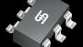
According to the datasheet, these LED controllers can be used in a variety of applications in which the maximum supply voltage is less than 40 V. It’s available in two package types (SOT26 and DFN2020); the DFN2020 package, with its low profile of less than 0.6 mm, makes this IC especially well-suited for edge lighting strips.
On a side note: The datasheet describes these parts as designed for driving "low-current LEDs." I think that many of us would not consider 350 mA, or even 200 mA, to be "low current" in the context of LEDs (considering that a typical surface-mount indicator LED might be driven with 5 or 10 mA). So remember that "low current" is a relative term.

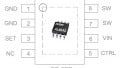
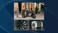
The BCR420U and BCR421U are both available in two package types. Images taken from the press release (PDF).
Easy to Use
In a previous article, we discussed another adjustable constant-current LED controller that requires the use of external switches (MOSFETs). Unlike that device, these ICs have "monolithically integrated transistors, diodes, and resistors," and consequently they are touted as being a rather simple solution for powering, and dimming, LEDs.
It is certainly noteworthy when a datasheet says "with no need for additional external components." It is indeed true that you can operate this device with not one external component, but chances are you won’t want to: The current through the LED is determined by the amount of resistance between the BJT’s emitter and ground. The IC comes with a default internal resistance of 95 Ω, which might give you an LED current of about 10 mA with a supply voltage of 3.3 V. If you want to customize the drive current, you need to add an appropriately sized resistor in parallel with the internal resistor (see the figure below).

Internal schematic and pin functions, from the datasheet (PDF).
The datasheet explains to us (in the Applications Information section on page 9) that the REXT vs. IOUT graphs should be used when determining resistor values for setting the LED current. However, it's not clear, at least to me, which resistor value should be used for achieving the maximum current value of 350 mA for the BCR421U device. While a resistor value of approximately 2 Ω should be used with the BCR420U for driving the maximum current of 200 mA, the BCR421U’s resistor value associated with 350 mA is not included in the plot. In fact, the plot stops at 200 mA, so apparently you’ll have to contact Diodes Inc. if you want to use an output current between 200 mA and 350 mA.

The datasheet doesn’t give us the resistor values needed for LED currents above 200 mA (for the BCR421U). Plots taken from the datasheet (PDF).
Dimming
The BCR421U allows for LED dimming by means of a PWM signal (up to 25 kHz) applied to the EN pin.

PWM dimming with the BCR421U. Diagram taken from the datasheet (PDF).
As indicated by the diagram, the PWM signal can easily be generated by a microcontroller and then connected directly to the EN pin. This is a pretty straightforward dimming arrangement, especially considering that the average LED intensity will be directly proportional to the PWM duty cycle.
Need More Current?
If you find that the maximum current capabilities of these ICs are not sufficient for your design requirements, then consider connecting two or more in parallel. The figure below (from page 9 of the datasheet) depicts such an arrangement.
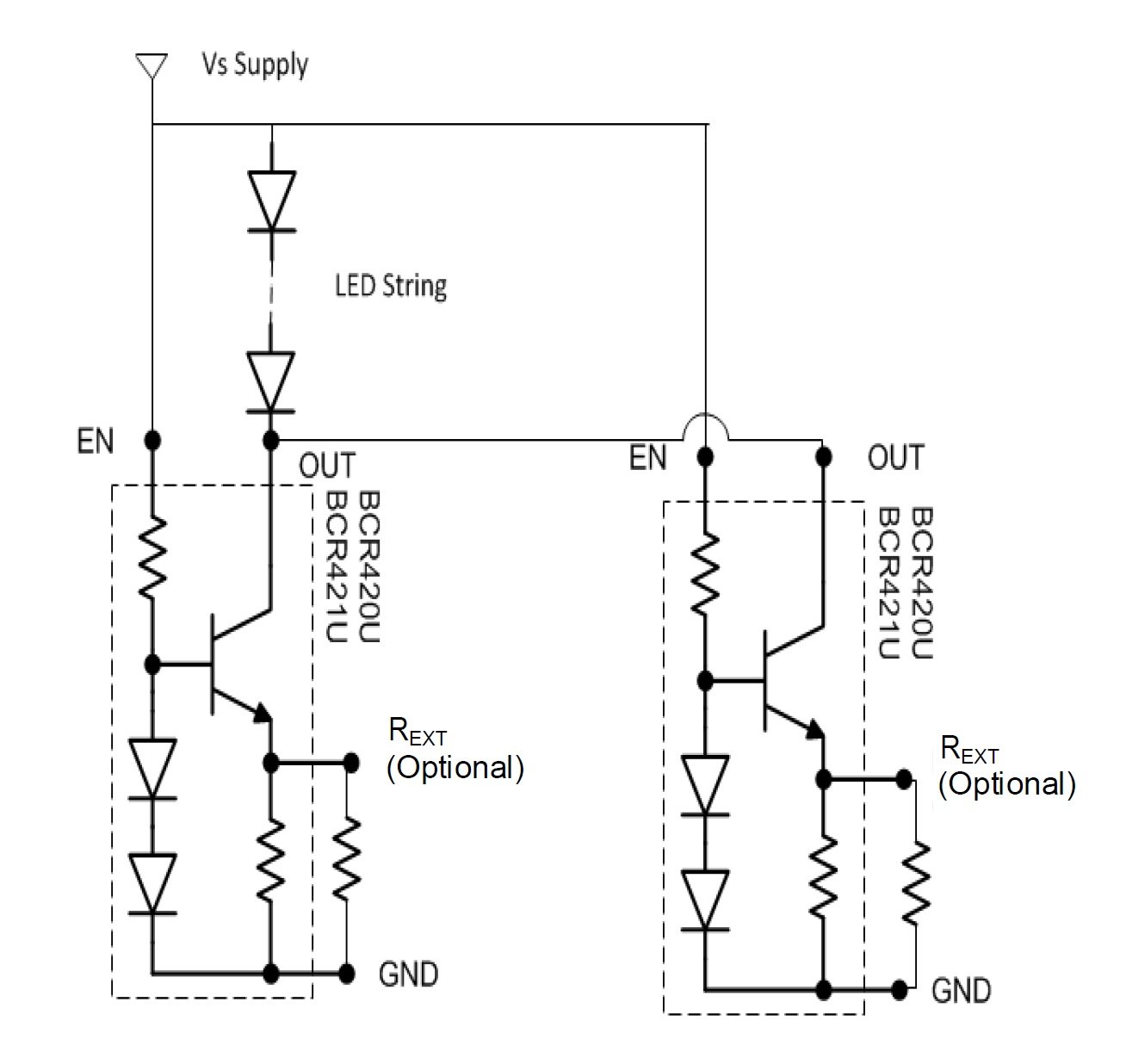
A parallel configuration allows for higher LED currents. Circuit taken from the datasheet (PDF).
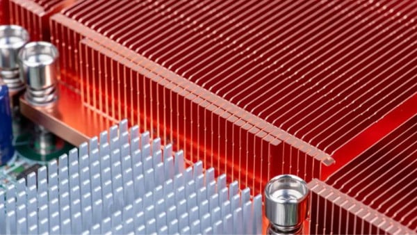
Power Dissipation
As is often the case when you’re dealing with circuits that are designed to actually drive some serious current through a load, you need to keep an eye on power dissipation and the associated thermal effects. So take a look at the six thermal-characteristics plots (on page 4 of the datasheet) and, if you’re unsure about whether you have provided adequate pathways for heat dissipation, consult a thermal engineer.
Have you had an opportunity to use either the BCR420U or BCR421 in any of your designs? If so, leave a comment and tell us what you think.
Related Content


Hi Nick, after I read your article I searched for the datasheet and found the way to set the current for 350 mA. It is the pict. 7 with an external Resistor of 2.1 Ohm. The current can be calculated approx. by the voltage of one Diode dividing by the resulting resistor of internal and external. (0,70 V / 2.1 = 333 mA)