 Facebook
 Google
 GitHub
 Linkedin
The Basics Behind Constant-Current LED Drive Circuitry
This technical brief discusses the reasoning behind and implementation of constant-current drive circuitry for illuminating LEDs.
This technical brief discusses the reasoning behind and implementation of constant-current drive circuitry for illuminating LEDs.
Just about anyone who works with electronics is familiar with constant-voltage LED drive, though it may not be recognized as such. The classic digital-output-plus-series-resistor arrangement is essentially a constant-voltage scheme; it may seem like the resistor is establishing a fixed current, assumed to be about (VDD – 0.7 V)/Rseries, but in reality the circuit is governed by the diode’s exponential current–voltage relationship.
The constant parameters here are VDD and Rseries; the current is then determined by the point at which the load line intersects the diode’s characteristic curve. Variations in this curve—and of course the curve is not identical from one part to another—can lead to variations in current.
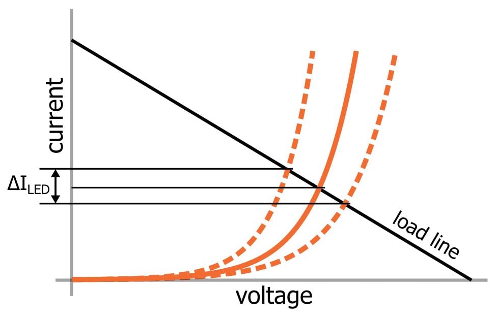
This approach is perfectly adequate for various noncritical LED applications. But there is an inherent weakness in any circuit that does not actually control the current through the LED, for the simple reason that forward current is more significant in terms of LED operation than forward voltage.
- An LED’s brightness is determined by forward current. This issue becomes somewhat foggy when you get down to the details because forward voltage is related to forward current according to the exponential relationship mentioned above. Thus it is difficult to separate current from voltage when considering the effect on brightness. But it makes sense to think of current as the quantity that determines brightness because the more or less linear relationship between forward current and brightness is much more straightforward and useful than the relationship between forward voltage and brightness. So if you want to make precise adjustments to brightness, you need to control the current.
- An LED can be damaged if the maximum forward current is exceeded. Applying too much voltage is not much of a concern because the voltage drop across the diode does not increase significantly after it enters the more vertical section of its exponential current–voltage relationship. What increases is not the voltage drop but the forward current, and this is the quantity that needs to be limited according to the specification in the datasheet. It’s easy to respect the maximum forward current spec when all you need is a simple indicator—you can use a series resistor sized such that the current is always far below the limit. But what if you want to maximize the LED’s luminous intensity—i.e., get as much light out of one LED as you can? In that case, you need to push the forward current out toward the maximum, and to safely do that, you need constant-current drive.
Perhaps the easiest way to implement constant-current LED control is with an integrated circuit designed to do precisely that—there are many such devices to choose from. These LED drivers incorporate a variety of helpful functionality; they can simplify your design and, thanks to energy-efficient features, help to extend battery life in portable applications.
For those who like to design their own circuits, an op-amp can provide adjustable constant-current LED drive:
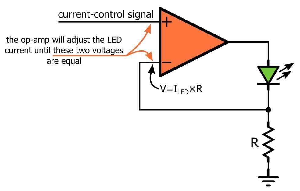
The negative-feedback action causes the op-amp to increase or decrease its output current until the voltage across the resistor matches the control voltage applied to the noninverting input terminal.


what i would like is a schematic for the “as seen on tv” led flashlight with the strobe circuit. even just the strobe circuit part as i can build 1&2 and on cell led flashlights now. I just can’t seem to get the “strobe that fiends off attackers” just right!