 Facebook
 Google
 GitHub
 Linkedin
Retro Teardown: Commodore 1541 Floppy Drive vs DVD Drive
CD drives are standard these days, but who remembers our old friend the floppy drive?
Many readers (including myself) where born into a world where 2GB of RAM is considered ancient and Windows 95 was a relic of the Jurassic period. CD drives are standard these days, but who remembers our old friend the floppy drive?
Floppy drives used to be the equivalent of the CD drive and were used to transfer files between computers and distribute software. Most are familiar with the classic 3 ½ inch floppy, but before these even existed, there were floppies at a staggering 5 ¼ inches in size (which could only hold up to 340kB).
So in this Retro Teardown, let’s have a look at a Commodore 1541! The Commodore 1541 is a disk drive attachment for the Commodore 64. We'll first take a quick look inside a DVD drive and compare it to the Commodore 1541 so we can fully appreciate how far we've come.

Image courtesy of Nathan Beach [CC BY-SA 2.5]
Size & Back Comparison

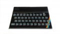
Size comparison of the CD drive on top of the Commodore 1541

Back of the Commodore 1541 (bottom) and CD drive (top)
The CD drive shown here uses an IDE cable which transfers parallel data (more modern CD drives use SATA) and a four-prong power connector (5V and 12V). The Commodore back shows a power connector (which requires mains voltage), a switch, fuse, and two six-prong pin connectors with a data transfer rate of 0.4kB/s.

Size comparison between a 5 1/4-inch floppy (up to 340kB) and a CD (up to 700MB)
CD Drive Internals: PCB and CPU

Internals of the CD drive
The CD drive shows a PCB and mechanical connectors for controlling the CD drive. The PCB uses a green solder mask with a black silkscreen (not as common as white). It can be seen that are are plenty of stitching via so this PCB could deal with analog-sensitive devices and/or generate a lot of noise.

CD drive motherboard
The motherboard shows only two major ICs and a power section of the circuit (upper left). The large IC in the center is a CD controller (MT1858L) but no datasheets can be found online.
The second chip is an R2A30232ASP which appears to be a six-channel motor controller manufactured by Renesas.
CD Drive Internals: Mechanism & Laser

The internal mechanism of the CD drive
The CD drive uses small stepper motors and worm gears to control the precise movement of the laser head (the small blue lens). A PCB jumper cable is used to connect the read/write head (which sits on rails) to the motherboard so that data can be transferred.

The CD read/write head PCB. Note the CD, GND, and DVD pins for the laser control
Here is a close up of the laser drive. The PCB is double-sided, two-layer solder mask and uses a white silkscreen legend. If you look carefully, you can spot the laser diode connections which say CD, GND, and DVD.
Floppy Drive Internals: CPU

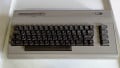
The inside of a very old Commodore 1541! Shoo, spiders! Shoo!
These are the internals of the Commodore floppy drive. Notice how all of the PCB is made with through-hole technology and socketed ICs. This makes it easier to repair because, if an IC should fail, it can be popped out and replaced with a new one.
The PCB is green with a foil finish on the copper (you can tell by the tin foil appearance of copper pour areas).

The major components in the floppy drive
Here we can see the chips that are the brains of the entire operation. The chips make up an entire 6502 based computer with the following chips:
- 6502 processor
- 6522 IO controller
- AM9128 2KB SRAM
- MOS325572 floppy controller
- 901229 ROM chip
- 325302 ROM chip
Strange to think that when you use this with a Commodore computer, you effectively have two machines!

6502 processor, 6522 IO controller, and two ROM chips (left)

A second 6522 IO controller, 325572 MOS floppy controller, and an AMD 2KB SRAM chip
Floppy Drive Internals: Power

Two linear voltage regulators for generating +5V and +12V
Here are two linear voltage regulators (7805 and 7812) providing +5V and +12V. You can tell by the package and size of the heatsinks that a lot of current is consumed by the drive during use!

Connectors used to connect the board to motor drives and the transformer
No ribbon cable or fancy PCB jumpers for the Commodore—big wires will do! These wires take power from the transformer underneath, control the motor, and the read/write head.
![]()
Underneath the PCB reveals the transformer and drive mechanism
Below the PCB sits the drive mechanism and the transformer.
Wrapping It Up!
It's amazing to see just how much technology has changed in a few decades as ICs get more powerful and smaller as the data density increases!
On the next Throwback Thursday, we will teardown the Sega Genesis! (also known as the Mega Drive)
Previous Retro Teardown : Speak and Spell
Featured image used courtesy of Nathan Beach [CC BY-SA 2.5]


In my time… These floppies were a huge improvement, compared with the cassette-tapes! I even had a text-processor running on C64 😉
Can you found the r2a30232asp Datasheet?
Very good, yes I’ve looked inside both, thing though, there = some 5¼” floppies with more than 340K, it = Commodore using 170k on 1 side.