 Facebook
 Google
 GitHub
 Linkedin
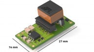
New Isolated IGBT Gate Driver from Analog Devices for Power Supplies and Photovoltaic Inverters
The ADuM4137, which incorporates fault detection and can also drive MOSFETs, is intended for photovoltaic inverters, power-supply circuitry, and motor-control applications.
The ADuM4137, which incorporates fault detection and can also drive MOSFETs, is intended for photovoltaic inverters, power-supply circuitry, and motor-control applications.
We often think of transistors as belonging to one of two categories: bipolar junction or field-effect. These devices certainly are the most common, but we shouldn’t forget about the transistor that is essentially a hybrid of the BJT and the FET: the insulated gate bipolar transistor (IGBT).

One version of the circuit symbol for an N-channel IGBT.
IGBTs are useful in high-power switching applications. Since the gate is insulated, it requires essentially zero input current, and then the BJT portion of the device provides a pathway for the load current. You can read more about IGBTs in the AAC textbook.
Turn-on and Turn-off Delays
The benefits associated with an insulated gate are, not surprisingly, accompanied by a disadvantage. The gate of a MOSFET or an IGBT has a capacitive structure, and this capacitance must be charged and discharged whenever the device is turned on or turned off.
High-current applications require physically larger transistors, and this leads to a higher gate capacitance. If you’ve ever wondered why gate-driver ICs exist, this is the first reason. A typical low-voltage digital output stage is not designed for quickly delivering large amounts of charge to the gate of an IGBT or MOSFET. Slow charge delivery results in slow switching, and this is why it is often beneficial to use a typical low-voltage signal to control a gate driver, and then the gate driver drives the transistor.
High-Side Gate Drive
Gate drivers also help us to overcome the complications associated with a shifting reference potential. Controlling a MOSFET or IGBT is quite straightforward in low-side circuit configurations— i.e., when the source or emitter is connected directly to ground. The gate voltage is referenced to the source or emitter voltage, which is always 0 V.
In high-side applications, though, the source or emitter voltage varies according to the state of the circuit, and the gate voltage must be adjusted accordingly. This can be particularly tricky when a drive circuit (such as a half bridge) is used to switch the highest voltage available in the system. When the high-side transistor is on, the source or emitter voltage is just slightly below the supply voltage, which means that the supply voltage cannot directly control the gate of the transistor.
An Isolated Driver
The ADuM4137 solves the problem of high-side gate drive by means of galvanic isolation. Electrical isolation between the input interface and the high-power switching circuitry allows the device to level-shift the input signals in accordance with the changing potential of the high-side source or emitter node. (This isolation is also a safety feature, because it protects low-voltage circuitry and human beings from dangerous conditions associated with faults that might occur in the high-power portion of the system.)
Perhaps the most familiar form of isolation is based on optical transmission, but Analog Devices favors magnetic coupling. The ADuM4137 uses iCoupler technology in conjunction with on-off keying encoding, as shown in the diagram below.

Diagram taken from the ADuM4137 datasheet.
The Block Diagram
The internal architecture of the ADuM4137 is a good reminder of the impressive complexity that is often hidden within an IC package.

Click to enlarge. Diagram taken from the ADuM4137 datasheet. Apparently isolated gate drive is not as simple as one might think....
The ADuM4137 provides a maximum drive current of 6 A; this very high output current helps to quickly turn on the IGBT. The device also includes a low-resistance turn-off transistor that functions as a discharge path for the gate. The internal propagation delays for both rising and falling edges are about 100 ns, and the plots below give you an example of overall turn-on and turn-off characteristics for a 100 nF capacitive load.


Plots taken from the ADuM4137 datasheet.
Have you come across any applications in which an IGBT is clearly superior to a MOSFET or BJT? Let us know in the comments section below.
Related Content


yes,
BLOWER
CENTRIFUGAL
BY
AMETEK
ROTRON TCHNICAL PRODUCT DIVISION
It is using 4 IGBT GN760B-220F
Induction heating applications, igbt’s are very tolerant of the arcing conditions that may occur in this process.