Facebook
 Google
 GitHub
 Linkedin
Accelerometer/Gyroscope Motion Tracking: A Tactical-Grade Inertial Sensor System from Analog Devices
The ADIS16495 from Analog Devices is a complete inertial system that includes a triaxis gyroscope and a triaxis accelerometer.
The ADIS16495 from Analog Devices is a complete inertial system that includes a triaxis gyroscope and a triaxis accelerometer.
Analog Devices recently released the ADIS16495 tactical-grade inertial sensor. This complete inertial system provides, according to the datasheet, a "simple" method for integrating accurate and multiaxis inertial sensors.
Analog Devices’ patented MEMS technology allows this device to offer ultra-low noise and stable sensing in the presence of shock, vibration, and temperature disturbances, so it may be a viable choice for applications such as avionics, unmanned vehicles, robots, and precision instrumentation.
_block_diagram.jpg)
The ADIS16495 is an inertial sensor system that includes a triaxis gyroscope and a triaxis accelerometer. Diagram taken from the datasheet (PDF).
A Multichip Design
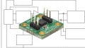
Given all the technological advances going on these days, we might expect to see all the features and goodies offered by this inertial sensor integrated into a single IC package. But, as it turns out, this "complete inertial system" is actually only available as a multichip module. And since this device is characterized as being "tactical grade" (understood, at least by me, as meaning "rugged/robust/etc."), it's not surprising to see this system contained in an aluminum package (see figure below).
_Device.jpg)
The ADIS16495 is available only in an aluminum 47 × 44 × 14 mm package. Image courtesy of Analog.com.
This unique package measures 47 × 44 × 14 mm and includes a standard interface connector that is designed to mate with Samtec connector CLM-112-02, or equivalent.
Gyroscope Sensors
In order to acquire accurate gyroscope measurements, this inertial system uses two digital MEMS gyroscopes for each of the three orthogonal axes (that is, x, y, and z); so, a total of six MEMS gyroscopes are used. The figure below illustrates how measurements from two gyroscopes are combined into one angular rate data stream.
_gyroscope_data.jpg)
When it comes to gyroscope measurements, the ADIS16495 utilizes two sensors for each of the three axes. Diagrams taken from the datasheet (PDF).
These same six gyroscope sensors are used, along with some calculus, for determining the delta angle measurements that, as described in the Delta Angle section of the datasheet (page 23), "represent a computation of angular displacement between each sample update." See the figure below for details.
_delta_angles.jpg)
Gyroscope data along with a bit of math gives you delta angle measurements. From the datasheet (PDF).
Acceleration Sensors
In addition to the six gyroscope sensors, the ADIS16495 also makes use of three accelerometers for providing dynamic and static acceleration data along the three axes (see the figure below). This acceleration data includes both linear acceleration measurements and delta velocity measurements; if you're not familiar with the term "delta velocity," the datasheet describes it as being a "computation of linear velocity changes" between each measured sample.
For detailed information on linear acceleration measurements and delta velocity data, check out the Acceleration Data section (page 21) and the Delta Velocity section (page 24) of the datasheet.
_acceleration_data.jpg)
Three accelerometers are used for determining linear accelerations and the related delta velocities in the three axes (x, y, z). Diagrams taken from the datasheet (PDF).
The SPI Interface and Device Operation
Communication with the ADIS16495 is possible via the SPI bus. And even though this inertial sensor offers information that is acquired, to some extent, in a complicated manner and then processed mathematically, the device is touted as being an autonomous sensor system that begins functioning as soon as power is applied to it; once its initialization phase is complete, the device automatically samples data, processes the data, and saves it in output registers that are accessible via the SPI port.
So, in other words, this powerful and complicated sensor system provides its measurement data via rather easy-to-access registers. The figure below shows, granted in a very basic manner, how this process works.
_signal_processing_diagram.jpg)
This is how the ADIS16495’s data is gathered, processed, and made available to the user. Diagram taken from the datasheet (PDF).
Have you had a chance to use this new tactical-grade inertial sensor in any of your designs? If so, leave a comment and tell us what you think.