Facebook
 Google
 GitHub
 Linkedin
Arduino Launches Plug-and-Play Modules for Long-Range Sensor Projects
With the three new boards, developers can seamlessly integrate complex I2C sensor networks with motor drive systems without the headaches of chaotic wiring.
Arduino's Modulino ecosystem provides modular sensor and actuator boards that streamline prototyping. Each module uses QWIIC connectors and the I2C protocol to simplify connection and programming of multiple nodes.
Recently, the company added three new boards that build on that vision: Modulino Hub for scaling up I2C sensor networks, Modulino Extender for reliable I2C communication over long cable runs, and Modulino Motors for high-current motor driving.

With the three new members of the Modulino family, designers now have 15 additional options for prototyping interactive devices. Image (modified) used courtesy of Arduino
In this article, we'll take a closer look at each module. But rather than jumping straight to specs, we'll start with the challenge each one was built to address, and then see how the board itself steps in to solve it.
Understanding I2C Address Conflicts
One of the most frustrating limitations of I2C in complex sensor networks is addressing conflicts, especially when using multiple sensors of the same type. On a standard I2C bus, each device must have a unique address so the microcontroller can distinguish between them. I2C uses a 7-bit addressing scheme, allowing a single bus to theoretically support up to 127 different devices.
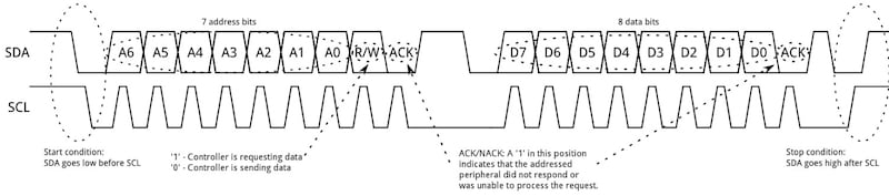
Typical I2C data transactions: the first seven bits after the start bit carry the device address. Image used courtesy of SparkFun
In an I2C data transaction, the microcontroller initiates communication by sending a start condition followed by an 8-bit frame. The first seven bits of this frame represent the target device's address, while the eighth bit is a read/write flag that tells the device whether the controller intends to send or receive data. Each device on the bus constantly monitors this address frame and only responds when it sees its own address, ignoring all other traffic.
While the theoretical address limit is 127, reaching that number in practice is rarely straightforward. The problem is that many sensors come from the factory with the same hardwired default address, often with only one or two jumpers or configuration options to change it. This severely limits the number of identical sensors you can use on a single bus.
Take Texas Instruments' TMP117 temperature sensor, for example. It uses a single hardware pin (ADD0) to support just four selectable addresses.
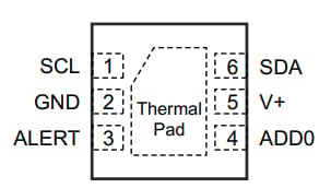
The TMP117 pinout diagram, highlighting the ADD0 pin used for address selection. Image used courtesy of Texas Instruments
The table below, adapted from the TMP117 datasheet, shows how the pin logic levels map to the available addresses.

The TMP117 address pin and the corresponding slave addresses. Data used courtesy of Texas Instruments
Since the sensor supports only four selectable addresses, you quickly hit a wall when you try to connect a fifth TMP117 sensor to the same I2C bus. The fifth sensor triggers address conflicts, causing data collisions or complete communication failure. Without extra hardware, you're often forced to swap sensors for different models or drastically limit how many you can use on a single bus.
The Modulino Hub
The Modulino Hub tackles the address conflict problem by creating eight independent I2C buses from a single main connection.
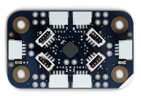
The Modulino Hub allows multiple same-address devices to coexist without conflict. Image used courtesy of Arduino
Built around Texas Instruments' TCA9548ARGER, the Modulino Hub functions as an I2C multiplexer, capable of routing the main bus to any combination of its eight channels. Each channel features its own pull-up resistors, acts as an electrically isolated bus, and can be independently enabled or disabled by writing to the device's control register.
Each bit in the control register maps directly to one of the eight downstream channels—bit 0 controls channel 0, bit 1 controls channel 1, and so on. By default, all channels are disabled after power-up, so no downstream devices are visible on the main bus until you explicitly enable them. Once a channel is enabled, any devices connected to it become fully accessible, allowing seamless communication with your peripheral modules.
Returning to our TMP117 example: eight of these sensors, all sharing the same address, can coexist across the Hub's eight channels without a single address collision.
The Hub itself requires its own address on the main bus, defaulting to 0x70. Three solder jumpers let you select any address from 0x70 to 0x77—allowing up to eight Hub boards on the same main I2C bus. This arrangement scales to 64 independent channels (8 Hubs × 8 channels each), making it possible to build complex sensor networks and fully modular systems without running into address conflicts on the main bus.
I2C's Distance Limitation
Another common limitation in I2C sensor networks is distance. Sensors are often located far from the controller—across a greenhouse, along a robotic arm, or across a factory floor. But I2C wasn't designed for long cable runs. To understand why, it helps to look at how an I2C bus drives its signals. Unlike push-pull solutions that actively drive lines both high and low, I2C uses an open-drain design: devices can only pull the bus down to ground. Returning to a logic-high state relies on pull-up resistors that pull the voltage back up.
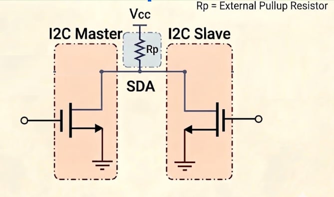
The I2C open‑drain bus diagram, highlighting the external pull‑up resistor Rp on the SDA line. Image used courtesy of the author
On a short PCB trace with low capacitance, the open-drain, pull-up method works well and produces the clean square waves a microcontroller expects. However, when the sensor is connected via a long cable, the added parasitic capacitance changes everything. Every meter of cable increases the bus capacitance, and the pull-up resistor must charge that capacitance to pull the line high: the more capacitance there is, the longer that takes.
With just a meter or two of cable, the rise time stretches to the point where a clean square wave turns into a slow, sloped ramp. Clock edges become harder to detect, and the bus may lock up or return corrupted data. For perspective, the I2C specification typically assumes a maximum bus capacitance of 400 pF, while a 10-meter cable alone can easily exceed 1,000 pF—more than doubling the allowed limit.
One obvious fix is to use smaller pull-up resistors to force faster rising edges, but this comes at a cost: the lower the resistance, the more current flows through the resistor when the line is pulled low, increasing power consumption. Furthermore, the same current must pass through the open-drain transistor when the line is pulled low. Push the resistance too low, and the transistor can no longer sink enough current to establish a valid logic low.
The Modulino Extender
The Modulino Extender is designed to solve the I2C distance issue. At its heart is the Analog Devices’ LTC4311, a bus accelerator that monitors the I2C lines and injects additional pull-up current only during low-to-high transitions.
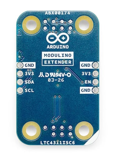
The Modulino Extender enables reliable I2C communication over long cable distances and with high-capacitance loads. Image used courtesy of Arduino
Unlike standard pull-up resistors that provide constant current—which can result in slow rise times when bus capacitance is high—this dynamic approach significantly increases the slew rate, maintaining clean square waveforms even over long cables. The figure below shows how the LTC4311 sharpens the rising edges of an I2C signal compared to standard pull-ups alone.
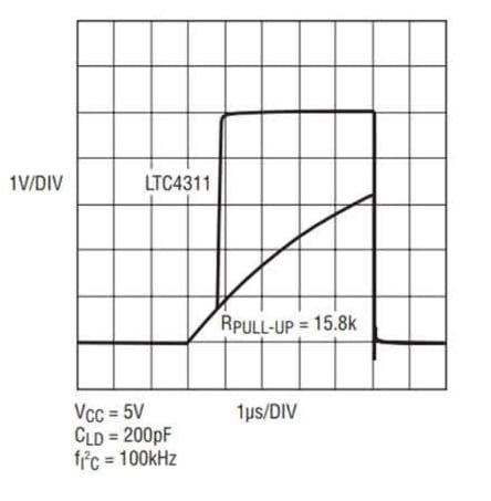
Comparison of I2C waveforms with and without the LTC4311 accelerator. Image used courtesy of Analog Devices
The acceleration is transparent to the I2C protocol, requires no configuration, and automatically handles both standard-mode (100 kHz) and fast-mode (400 kHz) communication. In testing, the Modulino Extender has delivered reliable operation with cables up to 30 meters in length.
Motor Control Challenges
One of the most common challenges in embedded projects is controlling motors—whether driving wheels, positioning a gimbal, or actuating a valve. Unlike sensors that typically draw milliamps and output clean signals, motors draw amps in abrupt bursts.
When a motor starts, it pulls a surge of current called inrush current, often several times its normal running current. When the motor is switched off, or PWM-controlled, the sudden interruption of current generates high-voltage spikes called inductive kickback. These spikes can travel back through the power lines, damaging microcontroller pins or corrupting nearby signals. These electrical disturbances are not rare edge cases; they occur in every brushed DC motor, solenoid, and stepper.
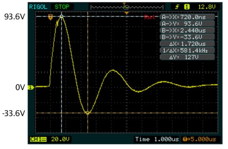
Oscilloscope measurement showing a voltage spike of up to 200 V (inductive kickback) generated when power is removed from a 24-V DC motor. Such spikes can damage sensitive electronics if not properly suppressed. Image used courtesy of Sealevel Systems
While engineers can build a functional driver by wiring a motor to a transistor or a basic H-bridge IC with a flyback diode, doing so requires juggling two distinct sets of design considerations. The first involves electrical safety: circuits need reverse-polarity protection, voltage transient clamping, and signal isolation to shield sensitive logic pins.
The second involves system management: reliable setups require active current sensing and thermal monitoring. If a motor encounters a stall condition—becoming mechanically blocked—it will draw enough sustained current to melt wires or destroy hardware in seconds. Furthermore, when a project scales to multiple motors or steppers, the physical wiring complexity and firmware overhead increase significantly, along with the likelihood of errors.
The Modulino Motors
The Modulino Motors module simplifies motor control by handling electrical safety and wiring on a single board.
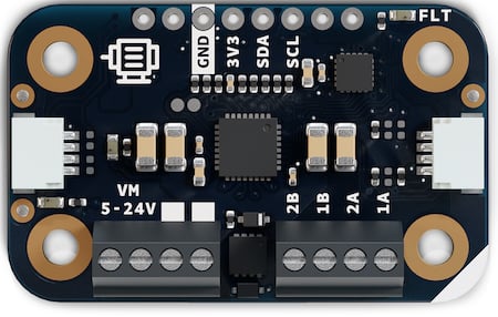
The Modulino Motors module features the STM32C011F6 microcontroller and MAX22211 dual H‑bridge driver. Image used courtesy of Arduino
The board features a dedicated STM32 microcontroller and a high-current MAX22211 dual H-bridge driver. By routing commands over an I2C bus via a standardized QWIIC connector, it offloads heavy firmware overhead and eliminates chaotic "spaghetti wiring". To protect the central microcontroller, the module isolates the low-voltage logic domain from the 5-V-to-24-V motor power domain. It also incorporates onboard Transient Voltage Suppression (TVS) diodes to clamp inductive kickback, along with hardware-level reverse-polarity protection.
Despite these hardware safeguards, the module does not seem to be designed for active current monitoring or automatic stall detection out of the box. While the driver provides baseline protection against catastrophic overcurrent, the system operates largely without sending real-time feedback back to your main controller. Consequently, developers should still practice defensive programming—such as using software timeouts—to handle mechanical stalls and protect the motor from prolonged stress.
Wrapping Up
By combining the Modulino Hub, Extender, and Motors modules, developers can seamlessly integrate complex I2C sensor networks with motor drive systems without the headaches of chaotic wiring. These boards streamline rapid prototyping for both the maker community and industry professionals. However, hardware convenience does not eliminate the need to understand a module's specific limitations within a target application.
Once the initial concept evaluation and prototyping phases are complete, engineers will likely still need to design a custom, application-specific circuit board to handle long-term deployment, optimized thermal management, and mass production.