Facebook
 Google
 GitHub
 Linkedin
Flux Adds Automatic Impedance Control For Simplifying High-Speed Design
The company’s new automated impedance control feature aims to make high-speed design accessible for engineers of all levels.
In the world of PCB design, few areas are more challenging to engineer than high-speed design. Considerations like impedance control, length matching, and signal integrity make this field particularly difficult and require a level of expertise that not all engineers have.
With this in mind, Flux is adding a new feature to its namesake browser-based PCB design tool, with the goal of easing the pains associated with high-speed design. Today, the company has announced the launch of a new Automatic Impedance Control feature to their tool. The new feature is designed to make impedance control a straightforward process.
In this article, we’ll take a look at the idea of impedance control in high-speed design and how Flux’s new feature hopes to simplify this pursuit.
What is Impedance Control?
All traces on a PCB, wires in our houses, or generally any channel that electrons pass through have electrical impedance. On a high level, impedance is a measure of the effective resistance to current flow that a given channel imposes on those electrons.
Impedance comes from aggregate contributions of the resistance, capacitance, and inductance of a channel. From a design perspective, impedance is a function of a trace’s dimensions such as height, width, and distance to reference GND. Notably, capacitive and inductive impedance are both functions of frequency and are not significant at low frequency or DC designs.

Trace impedance is a function of its geometry and spacing towards nearby signals and GND. From All About Circuits’ “Edge Coupled Microstrip Impedance Calculator”
However, once engineers start working with higher frequency designs (for instance, >50kHz) impedance starts becoming a consideration. Practically, many popular communication protocols, including USB, HDMI, PCIe, MIPI, SPMI, and DDR require some form of impedance control.
In impedance control, the impedance of a trace must be controlled to match the specifications of a given protocol, otherwise signal integrity issues such as reflections will start to impact performance.
Each of these communication protocols has specifications that tell you what their preferred characteristic impedances are, as well as the tolerances and other properties associated with them. For instance, USB Superspeed has a characteristic impedance of 90Ω.
Impedance Control as a Barrier
Unfortunately for the designer, there are a whole host of requirements that make impedance control difficult to implement. Not only does an engineer need to know that these requirements exist, but they also have to know how to implement them in their design software of choice.

Example impedance control calculator. From All About Circuits’ “Edge Coupled Microstrip Impedance Calculator”
Generally, the impedance control process consists of evaluating your PCB stackup, understanding how your signals are routed relative to the stackup, and using external calculators to determine what trace dimensions will meet your desired impedance. Finding the information necessary to calculate these variables takes time enough in itself, but actually implementing the impedance control is a whole other challenge.
The result of this existing workflow is that it’s incredibly hard for casual electronics designers and junior professionals to make some of the kinds of PCB boards they want to create.
Flux’s Approach and the Benefits
Flux has set out to address all the design challenges discussed above with today’s launch of its new Automatic Impedance Control feature.
Unlike traditional impedance control workflows where engineers must make use of specialized calculators which are external to the tool, Flux’s solution builds impedance control knowledge directly into the tool.
With its new approach, impedance control specifications are component properties. Here, all a user has to do is configure a signal to a given specification, and the tool will automatically calculate and handle impedance control for them.
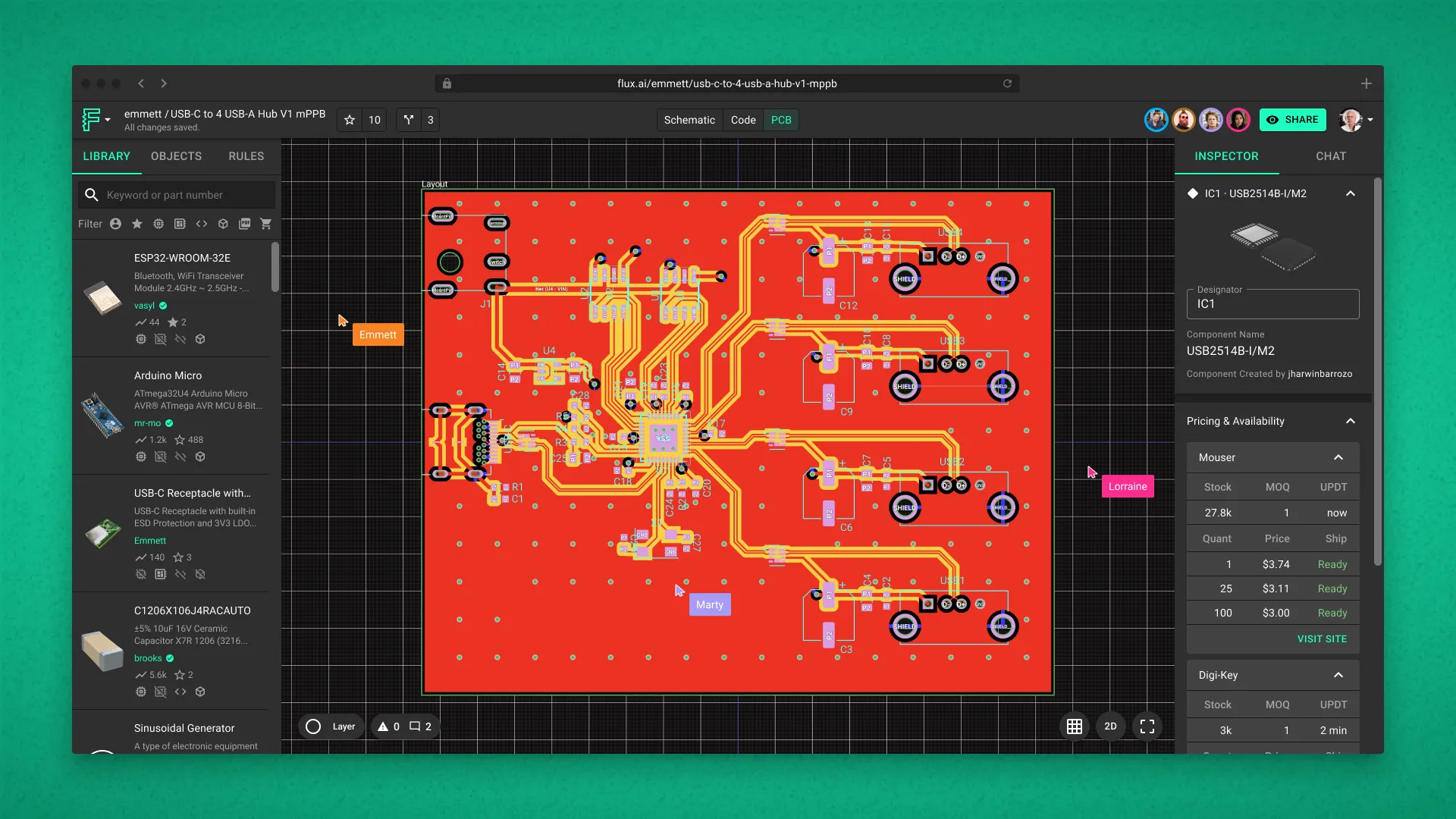
Flux’s new Automatic Impedance Control tool. Image used courtesy of Flux. (Click image to enlarge)
For example, if a user is routing a USB SuperSpeed signal, the user can just label the signal as “USB”, and the tool will automatically know that it needs a 90Ω differential impedance. Then, when it comes time for trace routing, the tool will automatically configure the trace dimensions according to the stack up to ensure the correct impedance is met. By doing this, Flux’s new feature effectively removes the work from impedance control and allows for the easy and carefree design of high-speed boards.
Simplicity for All EEs?
Ultimately, the new feature seeks to make PCB design easier by removing barriers to entry for non-expert designers. Yet, even expert designers will benefit from this tool as it simplifies the design process.
This highlights an ongoing challenge EEs face, where tools aren’t well integrated and knowledge is siloed off into different areas of expertise. In contrast, Flux’s new impedance control feature becomes more accessible to people who wouldn’t otherwise be able to do it. The result could be that hardware design becomes easier and more efficient for design engineers.