 Facebook
 Google
 GitHub
 Linkedin
A Temperature-Resistant Hall-Effect Sensor: A Digital-Latch Low-Voltage Sensor from TI
Texas Instruments has announced a new low-voltage digital-latch Hall-effect sensor with a wide operating temperature range.
Texas Instruments has announced a new low-voltage digital-latch Hall-effect sensor with a wide operating temperature range.
Texas Instruments (TI) recently announced a new Hall-effect sensor, the DRV5011. This sensor has a digital-latch feature, meaning that the output retains its logic level until a change in the magnetic polarity causes the output to transition. In other words, to toggle the IC’s output signal, the system must apply alternating north and south poles. Also, the IC operates at supply voltages down to 2.5 V, and it’s available in a super-small package measuring only 1.10 × 1.40 × 0.4 mm.
Here is TI's applications list for the DRV5011:

Figure 1. TI's recommended applications, from the datasheet (PDF).
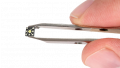
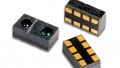
This IC is also offered in a larger package (an SOT-23) for those who like to solder by hand and don’t have an electron microscope handy. The image below shows the two packages available along with their pin descriptions.

Figure 2. SOT-23 and X2SON package and pin descriptions. Image taken from the datasheet (PDF).
A Curiously Wide Operating Temperature Range
One mildly surprising specification is the IC's wide ambient operating temperature range, specifically the extended upper temperature limit; according to the datasheet, this IC is rated for -40°C to 135°C.
The temperature limit of 135°C seems a bit odd and, if memory serves, I don't recall seeing other ICs with this limit. Furthermore, this value is actually greater than the upper temperature specification of military-grade ICs, which is 125°C, but the lower limit of -40°C is less than that of military-grade ICs (-55°C). I wonder if the 135°C value is simply a typo.
The table below shows the IC's operating ambient temperature range.

Figure 3. Operating ambient temperature range showing the rather odd upper limit of 135°C. Table taken from the datasheet (PDF).
Have you seen 135°C as the upper temperature specification on other ICs? Or do you know why this seemingly odd value may have been chosen for this IC? If you have any insights, please share them in the comments section.
High Magnetic Sensitivity
This Hall-effect sensor is advertised as having high magnetic sensitivity (±2 mT thresholds, see the table below) and “robust” hysteresis (4 mT).

Figure 4. Magnetic threshold and hysteresis characteristics, from the datasheet (PDF).
The following diagram conveys the IC's magnetic response.

Figure 5. A diagram showing the IC's magnetic response, from the datasheet (PDF).
A Seemingly Simple Device to Implement, and TI Offers Guidance
If you don’t have much experience with Hall-effect sensors, the DRV5011 may be a good sensor to start with because 1) it seems fairly user-friendly and 2) TI has provided helpful design guidance. As can be seen in the image below, TI gives clear information regarding how the DRV5011 should be mounted on a PCB with respect to the magnetic field.
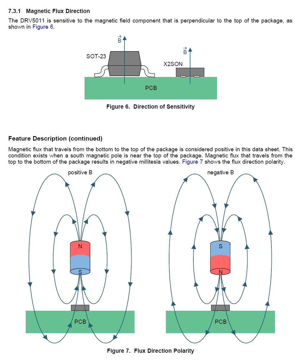
Figure 6. TI offers guidance on how to place the DRV5501 with respect to the magnetic field of interest. Diagram taken from the datasheet (PDF).
And if you're interested in knowing exactly where the magnetic sensing element is located within the IC itself, TI has also provided precise dimensions (as can be seen in the image below) for where to find it. Personally, I'm not sure why anyone would need, or want, to know where the sensing element is located. Perhaps this information may be important when placing the IC in extremely compact systems where the alignment of the sensing element with the magnetic field of interest is critically important...but this is just a guess. If you have an application example for which this information would be useful, please share your insights with us in the comments section.

Figure 7. TI provides the exact location of the magnetic sensing element within the IC. Diagram taken from the datasheet (PDF).
Finally, TI recommends some Do's and Don'ts when it comes to placing the DRV5501 with respect to a magnet's orientation, specifically a ring magnet that might be utilized in a knob-turning application (see the image below).

Figure 8. Correct and incorrect physical configurations, from the datasheet (PDF).
Have you had a chance to use this new digital-latch Hall-effect sensor? If so, leave a comment and tell us about your experiences.


It’s important to know where the sensor is situated because you need to know at what point in space the flux is being sensed, for example when teeth pass by it, similar to knowing where the light beam gets cut in an optical sensor. It’s also common to use pole pieces to focus the flux into the sensor, in which case it’s important to know where the sensor is, as well as having a thin package.
(That was in response to someone commenting: Personally, I’m not sure why anyone would need, or want, to know where the sensing element is located. Perhaps this information may be important when ...)