 Facebook
 Google
 GitHub
 Linkedin
Understanding and Applying the Hall Effect
Learn about the Hall effect and how it enables accurate, isolated current measurements.
The Hall effect was discovered by Edwin Hall in 1879, but it was many years before technological developments made it possible for integrated circuits to take full advantage of this phenomenon. Today, Hall effect sensor ICs offer a convenient way to achieve accurate current measurements that maintain electrical isolation between the measured current path and the measurement circuit.
Recommended Level
Beginner
From Lorentz to Hall
The Hall effect is an extension of the Lorentz force, which describes the force exerted on a charged particle—such as an electron—moving through a magnetic field. If the magnetic field is oriented perpendicular to the direction of the electron’s motion, the electron experiences a force that is perpendicular to both the direction of motion and the orientation of the magnetic field.

The Hall effect refers to the situation in which the Lorentz force acts on the electrons moving through a conductor, such that a difference in electric potential—in other words, a voltage—develops between the two sides of the conductor.

Note that the arrows in this second diagram indicate the direction of conventional current flow, meaning that electrons are traveling in the opposite direction. The direction of the Lorentz force is governed by a right-hand rule that takes into account the direction in which the electron is traveling relative to the magnetic field. In the first diagram, the electron is moving to the right, and the Lorentz force is upward. In the second diagram, with the electrons flowing to the left, the Lorentz force is downward, and thus negative charge accumulates toward the bottom edge of the conductor. The result is a potential difference that develops between the upper and lower edge of the conductor, with the upper edge more positive than the lower edge. This potential difference is referred to as the Hall voltage:
$$V_{Hall}=-\frac{IB}{eρt}$$
This equation, which applies to a current-carrying plate, tells us that the Hall voltage is related to the amplitude of current flowing through the conductor (I), the magnetic field strength (B), the elementary electron charge (e), the number of electrons per unit volume (ρ), and the thickness of the plate (t).
Harnessing the Hall Effect
The voltages generated via the Hall effect are small relative to the noise, offsets, and temperature effects that typically influence a circuit, and thus practical sensors based on the Hall effect were not widespread until advances in semiconductor technology allowed for highly integrated components that incorporate a Hall element and additional circuitry needed to amplify and condition the Hall voltage. Still, though, Hall effect sensors are limited in their ability to measure small currents. For example, the ACS712 from Allegro MicroSystems has a sensitivity of 185 mV/A. This means that a current of 10 mA would produce an output voltage of only 1.85 mV. This voltage may be acceptable if the circuit has a low noise floor, but if a 2 Ω resistor could be included in the current path, the resulting 20 mV output voltage would be a major improvement.
The Hall effect is relevant to a variety of sensor applications; devices based on this relatively simple relationship between current, magnetic field, and voltage can be used to measure position, speed, and magnetic field strength. In this article, however, we will focus on devices that measure current via the Hall voltage generated when a magnetic field induced by the measured current is concentrated toward an integrated Hall effect element.
Pros and Cons
Performance characteristics vary from one Hall effect current sensor to another, so it is difficult to precisely summarize the advantages and disadvantages of Hall effect sensing relative to the other common current-sense technique; namely, inserting a precision resistor into the current path and measuring the resulting voltage drop with a differential amplifier. In general, though, Hall effect sensors are valued for being “nonintrusive” and for providing electrical isolation between the current path and the measurement circuit. These devices are considered nonintrusive because no significant amount of resistance is inserted into the current path, and thus the circuit being measured behaves almost as if the sensor is not present. An additional benefit is that minimal power is dissipated by the sensor; this is particularly important when measuring large currents.
Regarding accuracy, currently available Hall effect sensors can achieve output error as low as 1%. A well-designed resistive current-sense circuit could surpass this, but 1% would generally be adequate in the high-current/high-voltage applications for which Hall effect devices are particularly suitable.
Disadvantages of Hall effect sensors include limited frequency range and higher cost. The ACS712 offers an internal bandwidth of 80 kHz, and the Melexis MLX91208, which is marketed as a “wideband” device, is specified up to 250 kHz. A resistive current-sense circuit with a high-speed amplifier, on the other hand, could operate well into the megahertz range. Also, as discussed above, the Hall effect is inherently limited in regard to measuring small currents.
Isolation
One of the dominant benefits of Hall effect sensors is electrical isolation, which in a circuit- or system-design context is often referred to as galvanic isolation. The principle of galvanic isolation is involved whenever a design requires that two circuits communicate in a way that prevents any direct flow of electrical current. A simple example is when a digital signal is passed through an opto-isolator, which converts the voltage pulses to light pulses and thus transmits data optically rather than electrically. One of the primary reasons for implementing galvanic isolation is to prevent problems related to ground loops:
.png)
Basic circuit design principles assume that interconnected components share a common ground node, which is assumed to be at 0 V. In real life, however, the “ground node” is composed of conductors having nonzero resistance, and these conductors serve as a return path for current flowing from the circuit back to the power supply. Ohm’s law reminds us that current and resistance make voltage, and these voltage drops in the return path mean that “ground” in one part of the circuit or system is not at the same potential as “ground” in another part. These differences in ground potential can lead to problems ranging from negligible to catastrophic.
By preventing direct current flow between two circuits, galvanic isolation enables circuits with different ground potentials to successfully communicate. This is particularly relevant to current-sense applications: a low-voltage sensor and processing circuit may need to monitor large, highly variable currents in, for example, a motor drive circuit. These large, rapidly changing currents will lead to considerable voltage fluctuations in the return path. A Hall effect sensor allows the system to both monitor the drive current and protect the high-precision sensor circuit from these detrimental ground fluctuations.
Common-Mode Voltage
Another important application for Hall effect sensors is current measurements involving high voltages. In a resistive current-sense circuit, a differential amplifier measures the difference in voltage between one side of a resistor and the other. A problem arises, though, when these voltages are large relative to the ground potential:
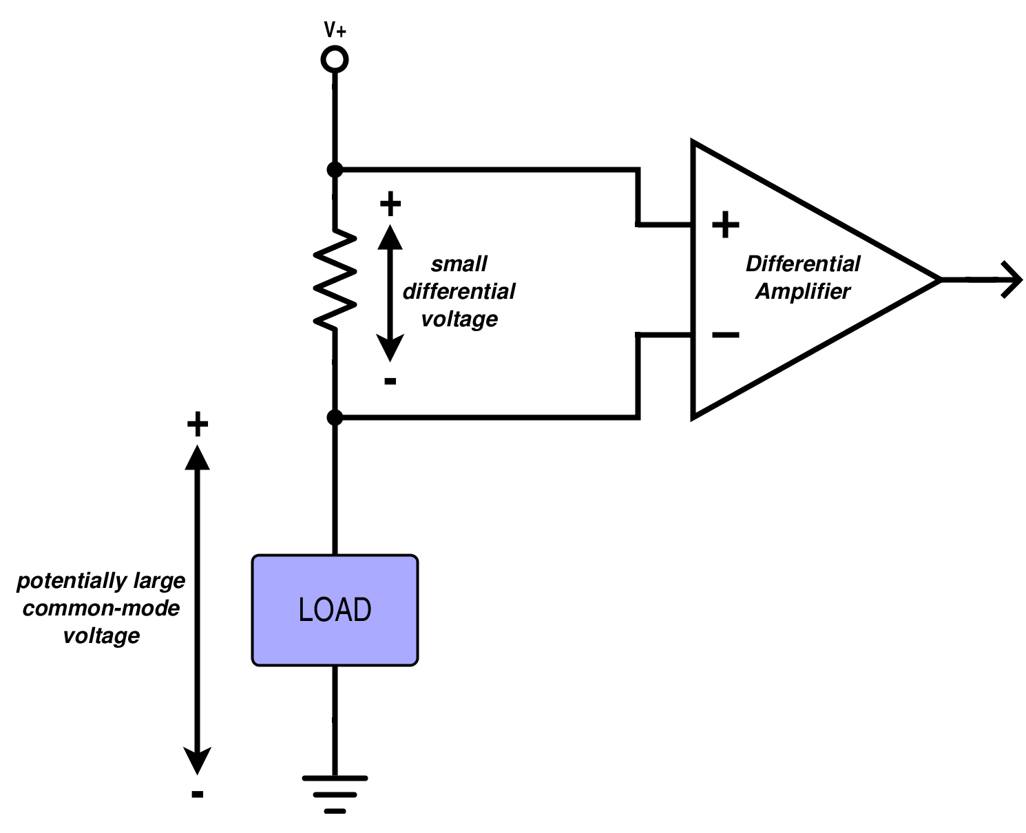
Real-life amplifiers have a limited “common-mode range,” meaning the device will not function properly when the input voltages, though small relative to each other, are too large relative to ground. Common-mode ranges of current-sense amplifiers typically do not extend beyond 80 or 100 V. Hall effect sensors, on the other hand, can convert current to voltage without reference to the measured circuit’s ground potential. Consequently, as long as the voltages are not large enough to cause physical damage, common-mode voltage does not affect the operation of a Hall effect device.
Related Content


Thank you Mr. Keim for this well written document. It helped me tie together a few concepts that I’ve been trying to understand for some time.