Facebook
 Google
 GitHub
 Linkedin
Hall Effect Position Sensing: Response Linearity and Slope for Slide-By Configurations
Learn about how various decisions regarding Hall effect sensing solutions—specifically for slide-by configurations—can effect your designs.
Hall effect sensors enable efficient solutions for position sensing. With Hall sensors, there is no mechanical connection between the sensor and the moving part, and, hence, a higher reliability and durability can be achieved.
There are several different magnet-sensor configurations that can be used in Hall effect-based position sensing applications. In this article, we’ll look at a slide-by magnetic configuration that can produce a linear Gauss versus distance curve. We’ll also see that it is possible to use a combination of magnets to adjust the slope of the Gauss versus distance curve.
Linearity Can Be a Decision Factor
In a previous article, we examined the simple head-on and slide-by configurations. These two arrangements are shown in Figure 1.
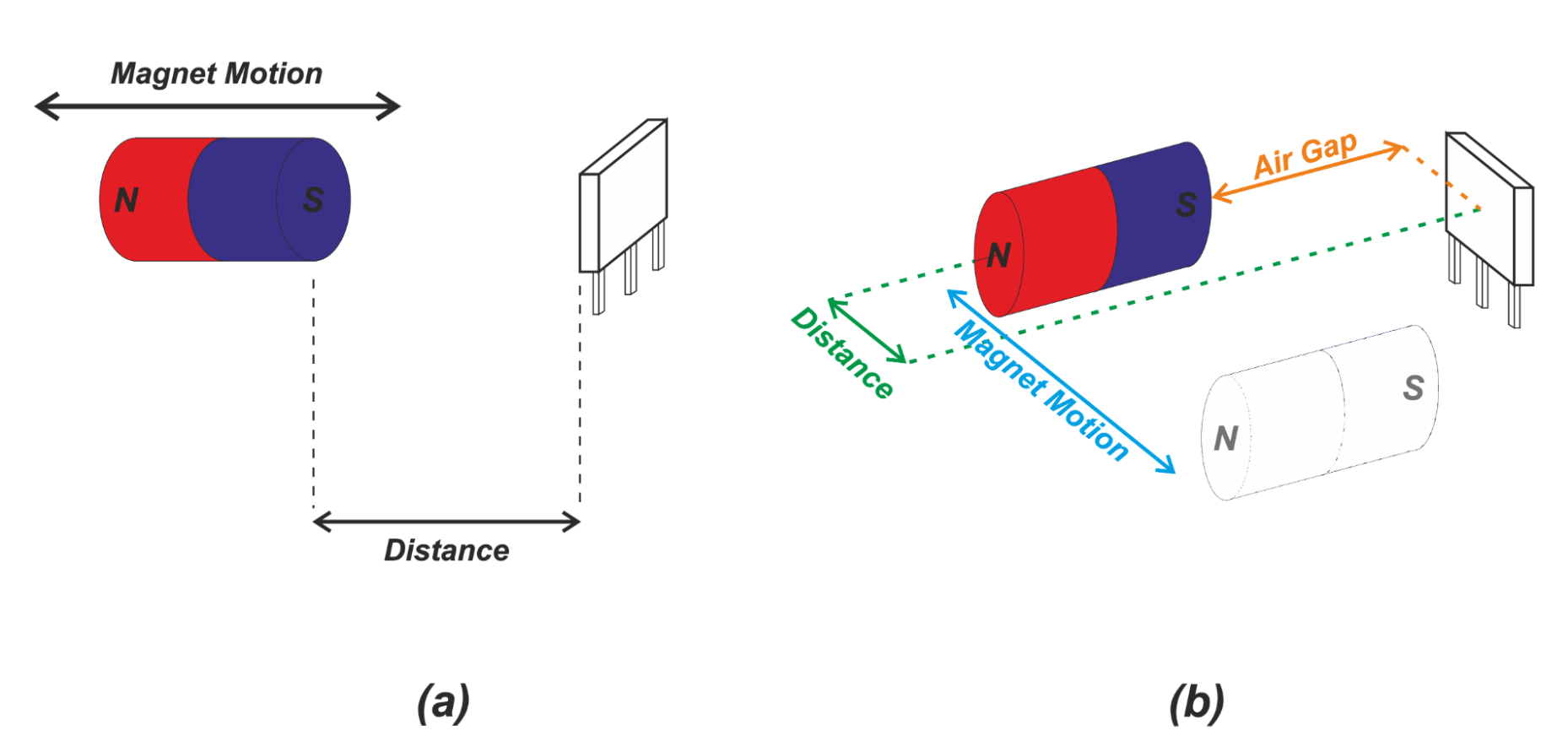
Figure 1 (a). Head-on and (b) slide-by sensing.
We saw that the relationship between the sensed field and distance is non-linear with the above arrangements. These magnet-sensor configurations are usually used as proximity detectors in applications where accuracy requirements are not very demanding.
However, when fine control of position along the sensing stroke is required, we prefer to have a linear relationship between the sensor output and displacement. In fact, although we can use software to remove the sensor linearity errors, having a linear response is desirable since it increases measurement precision and facilitates system calibration.
Linear Slide-By Sensing
Figure 2(a) shows a slide-by arrangement that exhibits a linear relationship between the z-component of the sensed magnetic field and the magnet displacement. Figure 2(b) shows the magnetic flux density (in the z-axis direction) versus magnet travel.
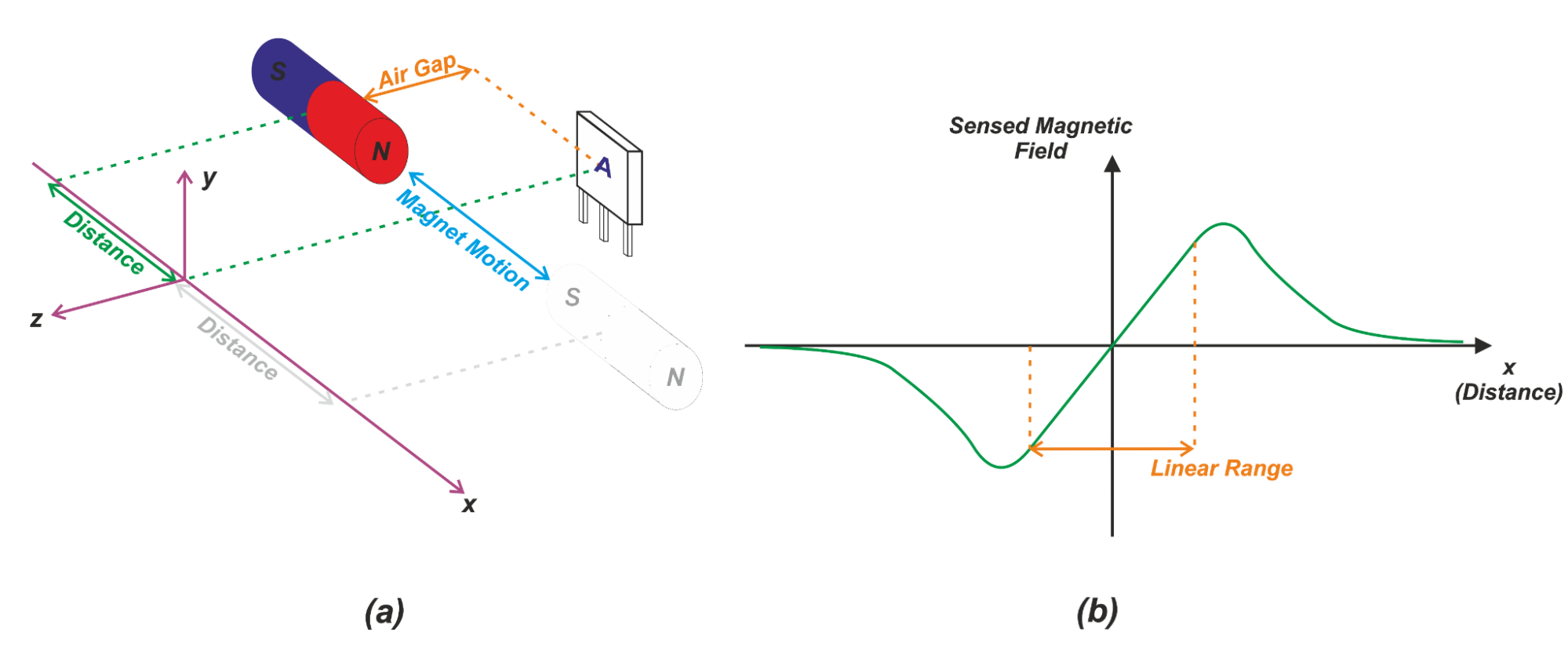
Figure 2 (a). A slide-by configuration with linear response (b) magnetic flux density versus magnet position
When the magnet is on the left side of the sensor (x<0), the magnetic field lines of the magnet produce a component in the opposite direction of the z-axis. Note that the field lines go from the north pole to the south pole of the magnet.
Figure 3 shows one of the field lines going through the sensor.

Figure 3. Direction of magnetic field lines through a Hall effect sensor
Hence, for x<0, the z-component of the sensed magnetic field is negative. When the magnet reaches the center position, the field in the z direction will be zero. For a positive displacement (x>0), the magnetic field will produce a component in the z-axis direction (positive magnetic field). For large displacements in either direction, a smaller number of the field lines can go through the sensor. Therefore, the magnetic field sensed by the sensor decreases.
One of the key features of this arrangement is that the z-component of the magnetic field exhibits a linear relationship with displacement around the origin. This linear range is shown in Figure 2(b). The length of the linear region is slightly less than the length of the magnet. For example, with a 22 mm magnet, the linear region can extend from about -10 mm to +10 mm. This linear behavior allows us to more easily and accurately detect the position of a moving object.
What If We Need a Larger Linear Range?
We can use a longer magnet to increase the linear range of the above configuration; however, certain applications cannot accommodate a large magnet in the system. Also, with long magnets, cost can be a limiting factor. If a stroke longer than the magnet length needs to be detected, we can use an array of sensors to extend the measurement range. This is shown in Figure 4.
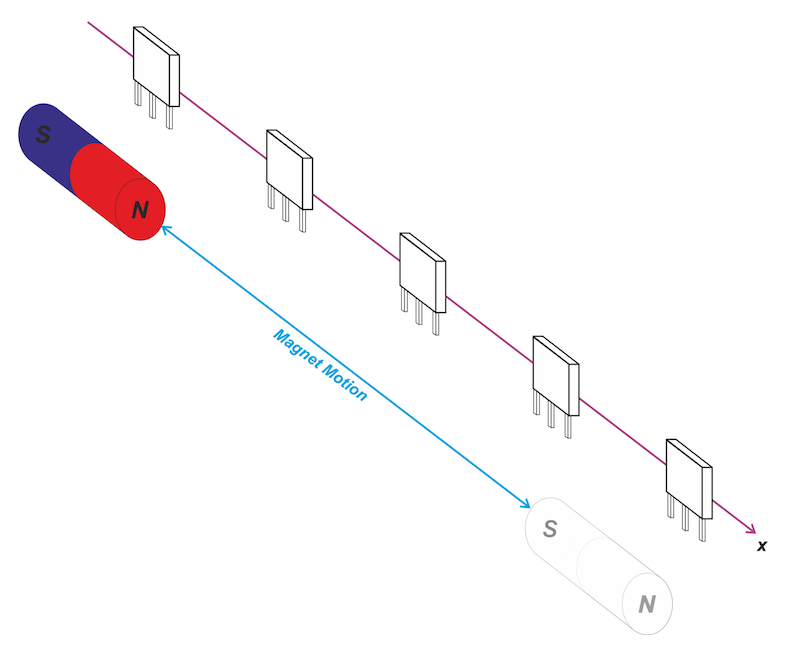
Figure 4. Using multiple Hall effect sensors for increased linear range
In this case, we need to process the data from more than one sensor to find the object position. For more details, please refer to this TI application note.
Detecting the Presence of an Object
The slide-by configuration in Figure 2 can also be used for detecting the presence of an object (rather than determining the object position over its stroke). Assume that in the example depicted in Figure 2(a), the magnet moves parallel to the x axis from left to right. Suppose that the magnetic operate and release points of our digital (ON/OFF) Hall effect sensor are as shown in Figure 5.
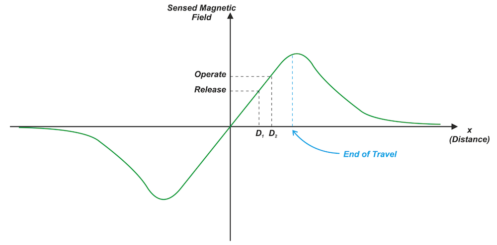
Figure 5. Using a slide-by configuration for ON/OFF sensing
As the magnet approaches the sensor from left to right, the magnetic field intensity becomes increasingly larger. At D2, the sensed magnetic field is equal to the magnetic operate point which turns the sensor ON. Bringing the magnet closer to the sensor leads to an even larger magnetic field and keeps the sensor ON.
Now, if we move the sensor in the opposite direction (from right to left), the magnetic field decreases. At D1, the magnetic field becomes smaller than the release point which turns the sensor OFF. This allows us to detect the object's presence. We can also use this structure to define a reference point (the switching point of the sensor) in the object stroke.
According to the magnetic flux density versus distance curve in Figure 5, a given magnetic flux density can be produced by two different displacements. That’s why the above arrangement is usually used in applications where the mechanical structure limits the end of travel of the object in a way that the sensor switching can happen only at one particular displacement. This prevents any ambiguity in the interpretation of the results.
Increasing the Gradient of the Gauss Versus Distance Curve
We discussed above that a digital (ON/OFF) Hall effect sensor can be used with the slide-by configuration to define a reference point in the object stroke. If we could increase the slope of the Gauss versus distance curve, we could detect the reference point with more precision.
With a larger slope, a given displacement leads to a larger change in the magnetic field intensity which can be more easily detected by the sensor. Figure 6(a) shows a magnetic system that exhibits a slope larger than that of the configuration in Figure 2(a).
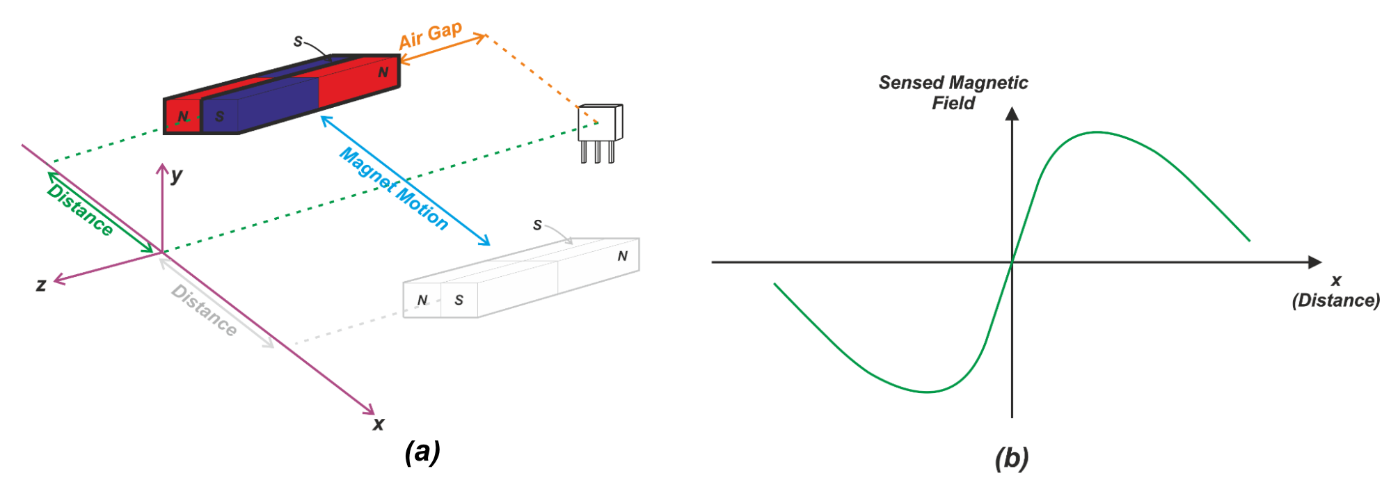
Figure 6. Using multiple magnets to increase field strength resolution
In this case, the north and south poles of a pair of magnets are moved in relation to the sensor. The overall field is determined by the field lines from both of the magnets. In this arrangement, distance is measured with respect to the center of the magnet pair. Figure 6(b) shows the z-component of the sensed magnetic field versus distance. At the center position (x=0), the number of the field lines from the north pole of one magnet that goes through the sensor is equal to the number of the field lines from the south pole of the other magnet. Hence, the net magnetic flux density is zero.
Assume that we move the magnet to the right from the center position (x>0). This abruptly increases the number of the field lines from the south pole and creates a magnetic field with a positive z-component. Similarly, as we move the magnet to the left from the center position (x<0), we obtain a relatively strong magnetic field with a negative z-component. Around the origin, the gradient of the curve is higher than that of the slide-by configuration in Figure 2(a) because the transition from north to south poles occurs abruptly. This relatively larger slope of the Gauss versus distance curve can help us define the reference position of a moving object with more accuracy.
There are two other interesting variants of this slide-by configuration. One version separates the two magnets by a small fixed distance. This allows us to have a less abrupt transition from north to south poles and hence, adjust the slope of the response around the origin. Another version uses a combination of three magnets. This can create a symmetric response with large slopes in either direction. A symmetric response can be useful when detecting deviation from a center line. To learn more about these two configurations, please refer to the “Hall Effect Sensing and Applications” manual from Honeywell.
To see a complete list of my articles, please visit this page.
Related Content