 Facebook
 Google
 GitHub
 Linkedin
Using Gilbert Multipliers as Phase Detectors in PLLs
This article explores the operation of the Gilbert-cell phase detector for both small and large signals.
An earlier series examined the classical phase-locked loop (PLL) from a system perspective, emphasizing its linear behavior. We'll now turn our attention to the characteristics of different phase detectors and how they affect different performance aspects of a PLL.
There are three main types of phase detectors:
- Analog multipliers and mixers.
- Digital phase detectors.
- Sampling phase detectors.
Analog multipliers are the most commonly utilized phase detectors in PLLs that operate with sine-wave inputs and sine-wave voltage-controlled oscillators (VCOs). They are often designed using a Gilbert-type architecture. Figure 1 shows the core structure of the Gilbert multiplier.

Figure 1. The basic Gilbert multiplier.
To understand how the Gilbert multiplier operates, you can check out my previous article. In this article, we'll explore the use of the Gilbert cell as a phase detector under three distinct conditions:
- When both inputs are small sinusoidal signals.
- When one input is a small sine wave, and the other is a large square wave.
- When both inputs are large square waves.
To begin, let's examine the phase detector when both inputs can be treated as small signals.
Phase Detection With the Gilbert Cell: Both Inputs at Low Levels
When both inputs are small, the output of the Gilbert cell is the product of the two inputs. Recall that in the context of the basic Gilbert multiplier, an input is considered small if it is much less than twice the thermal voltage (2VT).
Consider two input sinusoids with the same frequency (ωc) but different phases:
$$V_1 ~=~ A_1 \cos(\omega_c t~+~ \phi_1) \quad \text{and} \quad V_2 ~=~ A_2 \cos(\omega_c t~+~ \phi_2)$$
Equation 1.
Using a basic trigonometric identity, the signal at the output of the multiplier is obtained as:
$$V_{out1} ~=~ \frac{1}{2}A_1 A_2 \big [ \cos(2\omega_c t~+~ \phi_1 ~+~ \phi_2) ~+~ \cos(\phi_1 ~-~ \phi_2) \big ]$$
Equation 2.
The output includes components corresponding to both the sum and the difference of the input sinusoids' arguments. The multiplier phase detector is followed by a lowpass filter that removes the sum frequency component, leaving only the difference component:
$$V_{out} ~=~ \frac{1}{2}A_1 A_2 \ \cos(\Delta \phi)$$
Equation 3.
where Δϕ = ϕ1 – ϕ2.
Equation 3 shows that, for a given phase difference, the output of the phase detector is a DC term. The phase detector output varies sinusoidally with Δϕ, as illustrated in Figure 2.

Figure 2. The phase detector's output vs. its input phase error when both inputs are small. The circuit acts as an analog multiplier.
By differentiating Equation 3 with respect to the phase difference, we can determine the phase detector gain:
$$k_d ~=~ \frac{d}{d ( \Delta \phi) }V_{out} ~=~- \frac{1}{2} A_1 A_2 \ \sin ( \Delta \phi)$$
Equation 4.
The phase detector gain isn't constant. Instead, it changes with Δϕ. At Δϕ = 0, the gain is zero. For Δϕ = 90 degrees, which corresponds to the locked condition, the phase detector gain reaches its maximum value of:
$$k_d \Big \vert_{\Delta \phi = \pi/2} ~=~- \frac{1}{2} A_1 A_2$$
Equation 5.
For a multiplier phase detector, the characteristic remains monotonic if the phase difference from the lock point doesn't exceed ±90 degrees. In other words, the gain's sign reverses when the input phase difference deviates from its center value by more than 90 degrees.
The phase detector gain is a function of the input amplitudes (A1 and A2). This is undesirable, as it causes the PLL's static and dynamic behavior to be influenced by the amplitude of the input signals.
As a final note, the analysis above assumed that the two inputs to the phase detector are at the same frequency. If this assumption is not met, the difference frequency component generated by the multiplier is not a DC term and will be filtered out by the subsequent lowpass filter, resulting in a zero average output. This demonstrates that a multiplier phase detector cannot function as a frequency detector.
Phase Detection With the Gilbert Cell: One Input at High Level
In many practical scenarios, one or both of the multiplier's inputs can be closely approximated by a large square wave. In this section, we'll examine what happens when one input is small and the other is a large square wave.
In this case, we commonly apply the small sinusoidal signal to the lower differential pair (Q5 and Q6). The square wave is applied to the cross-coupled pairs of the Gilbert cell (transistors Q1 through Q4). If the square wave amplitude is sufficiently larger than 2VT, then two of the four transistors in the cross-coupled pair alternately turn completely off and the other two conduct all the current.
By using the Gilbert cell schematic presented in Figure 1, you can easily confirm that the circuit transfers the sinusoidal input to the output with either its original or inverted polarity during the two half-cycles of the square wave. To help us visualize this, the following two figures show the typical waveforms for this scenario. Figure 3 shows the input waveforms.

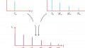
Figure 3. The small sinusoid (top) and the large square wave (bottom) applied to the Gilbert cell.
The output waveform is illustrated in Figure 4.

Figure 4. The output waveform of the Gilbert cell when one of the inputs is a square waveform.
Note how the polarity of the sinusoidal wave alternates with each half-cycle of the square wave.
When you compare the input and output waveforms shown in Figures 3 and 4 with those from double-balanced AM modulators, such as the ring modulator, you'll see that both circuits generate identical waveforms. This suggests that the Gilbert cell can serve two distinct functions: as a phase detector and as an AM modulator.
To investigate the circuit operation as a phase detector, let's derive an equation for the output signal. We first note that the square wave switching between ±1 V can be expressed using the following Fourier series expansion:
$$V_1 (t) ~=~ \frac{4}{\pi} \cos( \omega_c t) ~-~ \frac{4}{3 \pi} \cos( 3 \omega_c t) ~+~ \frac{4}{5 \pi} \cos(5 \omega_c t)~-~ \ldots$$
Equation 6.
The sinusoidal input (V2) is multiplied by each of the frequency components presented in the equation above to generate the output waveform. However, since a lowpass filter is typically used after the multiplier, only the frequency component at ωc can influence the output of the lowpass filter. Consequently, the overall input-output behavior of the multiplier-lowpass filter combination resembles the previous mode of operation, with the exception that the fundamental frequency component contributing to the output has an amplitude of 4/π.
If we assume that the square wave (V1) has a phase difference of Δϕ with the sinusoidal wave (V2), we can substitute A1 = 4/π into Equation 3 to derive the phase detector's input-output characteristic:
$$V_{out} ~=~ \frac{1}{2}~\times~ \frac{4}{\pi} ~\times~ A_2 \ \cos(\Delta \phi) ~=~ \frac{2}{\pi} ~\times~ A_2 \ \cos(\Delta \phi)$$
Equation 7.
Note that the input-output characteristic described by the above equation resembles that of the previous mode of operation plotted in Figure 2, differing only in the scaling factor.
When V1 is sufficiently larger than 2VT, the transistors Q1 through Q4 operate as switches that either block or conduct the current determined by the differential pair consisting of Q5 and Q6. Regardless of the specific levels between which V1 toggles, the sinusoidal signal V2 appears at the output with either its original or inverted polarity. As a result, the phase detector gain is no longer a function of V1, as it was in the previous mode of operation (compare Equations 3 and 7).
The CMOS Gilbert Cell
As we discussed in the previous article, when inputs applied to the Gilbert cell are small, the circuit leverages the exponential transfer function of bipolar transistors to perform multiplication. However, when V1 is significantly larger than 2VT, the transistors in the cross-coupled pair (Q1 through Q4) operate as switches and their specific nonlinearity characteristics are not important.
In such cases, it's possible to use MOS transistors to implement the circuit. This implementation of the Gilbert cell is shown in Figure 5.

Figure 5. Gilbert cell built using MOS transistors.
Phase Detection With the Gilbert Cell: Both Inputs at High Levels
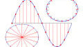
The last scenario we'll examine is when both inputs are large. This results in all transistors functioning as switches. Figure 6 illustrates the typical input and output waveforms for this scenario, denoting the phase difference between the inputs as Δϕ.

Figure 6. The typical waveforms when both inputs are large.
Similar to the previous mode of operation, we can apply the results of the Fourier analysis to determine the output when both signals are large and approximate a square wave. In this case, however, analyzing the waveforms in the time domain is more straightforward.
Similar to the previous modes of operation, a lowpass filter is incorporated after the Gilbert cell to compute the waveform's average value. When the phase difference (Δϕ) is 90 degrees, the output has a duty cycle of 50%. A duty ratio of 50% yields an average of 0 V.
When the phase difference deviates from 90 degrees, the output duty cycle is no longer 50%, resulting in a non-zero DC value that is proportional to the phase difference. For Δϕ = 180 degrees, the output is consistently equal to –RLIEE. For Δϕ = 0 degrees, the output is consistently RLIEE.
By calculating the average value of the output waveform for various values of Δϕ, we can derive the input-output characteristic (Figure 7).

Figure 7. Phase detector average output vs. input phase difference when both inputs are large.
Unlike the previous modes of operation, the phase detector gain is constant in this case and can be expressed as:
$$k_d ~=~ -\frac{2R_L I_{EE}}{\pi}$$
Equation 8.
As we observed above, the gain doesn't depend on the input signal amplitude. This makes the Gilbert cell a better choice for large signals.
If we examine the waveforms for this mode of operation more closely, we find that they share the same shape as those produced by a digital exclusive-NOR gate. Therefore, a digital XNOR gate and an overdriven analog multiplier exhibit identical performance when utilized as phase detectors.
Wrapping Up
This article delved into how the Gilbert cell functions as a phase detector in three different scenarios. When both inputs are considered small signals or only one of the inputs is large, the phase detector output varies sinusoidally with the phase difference (Δϕ). However, when both inputs are large square waves, the phase detector gain is constant.
When possible, it's preferable to use a Gilbert cell with larger signals. However, a drawback of this phase detector is that its output depends on the duty cycle of the input square waves. Consequently, any changes in the duty cycles caused by nonidealities can introduce a static phase error in the PLL.
All images used courtesy of Steve Arar


Very interesting article 👍🏻
Can this topology be used to generate modified sine wave AC for driving synchronized motors inhome appliances? Such as switching a MOSFET with sinusoidal time step?