Facebook
 Google
 GitHub
 Linkedin
Precise Incline Measurement: A High-Stability 3-Axis Digital Accelerometer from STMicroelectronics
This article takes a look at the IIS3DHHC three-axis accelerometer from STMicroelectronics.
This article takes a look at the IIS3DHHC three-axis accelerometer from STMicroelectronics.
STMicro describes the IIS3DHHC as low-noise and high-stability, important factors in an IC aiming to suit precision applications. According to its datasheet, it could be used in leveling, incline measurement, and positioning of systems such as antennas.

Graphic depicting the positive accelerations in three orthogonal axes.
Measurement Details and Possible Markets
This triaxial accelerometer from STMicroelectronics has a ±2.5 g (g = 9.807 m/s²) range and a 16-bit data output—that provides a minimum acceleration detection of $$\frac{5\cdot 9.807 \; \tfrac{\text{m}}{\text{s}^2}}{2^{16} \; \text{bits}}\approx7.482\times10^{−4} \; \tfrac{\text{m}}{\text{s}^2}$$.
If used as an inclinometer, that corresponds to approximately 12-16 arc-seconds of division; 16 arc-seconds is an error of 5 inches over a 1-mile distance. To put it another way, if you attached this IC to a meter-stick, and then placed a single human hair under one end of the meter stick, this accelerometer should be able to detect that the angle of inclination has changed.
Unfortunately, this accelerometer has 2% full-scale nonlinearity, which means that, depending on the angle, the measurements can be off by as much as ±50 mg. In other words, the device can notice that a hair has been placed under the end of the meter stick, but the measurement might be off by the width of a baseball.
This level of precision allows this IC to act as an accurate inclinometer for antenna aiming, platform leveling, or machinery feedback loops. For reference, a NEMA17 stepper motor similar to the type used in 3D printing has a minimum resolution of around a dozen arc-minutes (using 1/16 step divisions.) And a Starrett machinist level has a precision of 80-90 arc-seconds.
This device might also find a market in determining building and structure health—a sagging bridge or a leaning building can be diagnosed long before cracks or other failures show. Or perhaps seismologists might use it to track shifting ground around an active volcano.
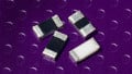
Device Footprint and Pin Function

Footprint for the IIS3DHHC
ST chose an interesting footprint for this device—the ceramic cavity land grid array (CC LGA). The design is similar to that of a quad flat no-leads (QFN) package except that pin 1 starts in the middle of the device (instead of at a corner), and the pins at the corners have mitered edges to allow for a smaller overall package.

The ceramic cavity LGA-16 package
Fully half of the pins (9-16) are connected to ground and another two provide input power (7-8). This leaves four pins for the Serial Peripheral Interface and two pins to act as programmable interrupts.
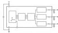
Inside the IC
The triaxial accelerometers send data to an analog-to-digital converter (ADC), which passes data to a digital filter. The filtered data is sent to a FIFO buffer or directly to the SPI.

Signal processing within the IIS3DHHC.
The low-pass filter can be configured to act as a finite impulse response (FIR) or an infinite impulse response (IIR) filter with a cutoff frequency of either 235 Hz or 440 Hz. The output data is updated at 1100 Hz, i.e., the device produces 1100 acceleration data points per second.
Interrupt pins can be configured to notify a host processor that the FIFO threshold has been reached, that the FIFO buffer is full, or that a buffer overrun has occurred. The FIFO threshold level is configurable (0 to 31).
The FIFO can be configured in a variety of modes. “Bypass mode” does not use the FIFO memory; data is sent directly to the SPI. “FIFO mode” passes data to the buffer until the buffer is full—then it stops collecting new data until that old data is offloaded by the host processor. In “continuous mode,” the FIFO memory will fill and then begin overwriting previously stored data. A fourth mode, “continuous-to-FIFO,” allows the host processor to switch between continuous and FIFO mode by using the first interrupt pins as an input, rather than an output. Finally, “bypass-to-continuous mode” switches between bypass and continuous modes based on the value of that same interrupt pin.
A built-in temperature sensor can provide 12-bit ambient temperature measurements in two’s complement format. The temperature sensor is intended to provide internal acceleration measurement compensation for the device. You can also use the temperature data to perform external compensation in a host microcontroller.
But compensating via a microcontroller isn’t terrifically straightforward since the relationship between temperature and acceleration offsets is not stated. Datasheets from other manufacturers will often provide a second or third-order polynomial that describes offset compensation. You should also know that the temperature data does not update as frequently as the acceleration data (it does not really need to since temperature is more stable than acceleration). Expect an update rate of approximately 68 Hz. The device has a stated stability of <0.4 mg/°C.
Calibration
ST provides “design tip” DT0053, which describes a method of performing a six-point tumble sensor calibration. The sensor is mounted in its final enclosure (provided that the enclosure has right-angle sides) and moved from position to position to collect values. The values are used to calculate cross-axis gains (for example, perhaps the x-axis measurement is affected partially by the z-axis measurement), as well as calculate acceleration offsets.
.jpg)
6-point tumble calibration from DT0053
This method determines any individual axis offsets and cross-axis gains and uses them to generate a transformation matrix. Then all measured accelerations $$A_n$$ are fed into the matrix to generate new acceleration values $$A_nʹ$$ that more closely coincide with the real-world acceleration.
$$\left(\begin{array}{c} A_X‘ \\ A_Y‘ \\A_ Z‘ \\\end{array}\right)=\left(\begin{array}{cccc} A_{X\text{gain}} & A_{Y to X} & A_{Z to X} & A_{X\text{offset}} \\ A_{X to Y} & A_{Y\text{gain}} & A_{Z to Y} & A_{Y\text{offset}} \\ A_{X to Z} & A_{Y to Z} & A_{Z\text{gain}} & A_{Z\text{offset}} \\\end{array}\right)\left(\begin{array}{c} A_X \\ A_Y \\A_ Z\\1 \\\end{array}\right)$$
ST also provides the IIS3DHHC carrier board to allow you to experiment with the sensor before you integrate it into a final design.

The evaluation board from the IIS3DHHC. Image from STMicro.com
This EVM is a simple carrier board that is designed to plug into the STEVAL-MKI109V3 motherboard.
STMicro’s software libraries should allow a user to get up and running rather quickly. Alternatively, users can interface the IC to a host microprocessor of their choosing—SPI has been around for so long that just about everyone knows how to use it.

STEVAL-MKI109V3 motherboard can interface directly to the IIS3DHHC eval kit.
What's Missing?
I personally would like to see some graphs that illustrate the accelerometer linearity over the measurement range. The datasheet mentions that the device’s non-linearity is 2% FS. The full-scale range is ±2.5g, and 2% of that is ±50 mg, which is a non-trivial amount. That corresponds to around 10 of the 16 measurement bits that drift away from the actual value.
Without knowing which way the device drifts, which orientations are most impacted, by how much, and in which directions, it becomes very difficult for an engineer to use this device correctly in applications that measure absolute inclination. As an example, an angle gauge for a CNC machine might be accurate at 0° pitch, but inaccurate when reading a 45° pitch (when the machine is actually several degrees from that position).
What types of products have you found 16-bit accelerometers in? Let us know below.
Related Content