 Facebook
 Google
 GitHub
 Linkedin
How Does Qi, the Wireless Charging Standard, Work?
Qi-certified wireless charging devices are now commonplace in the consumer market. But how exactly does Qi achieve wireless power transfer at the circuit level?
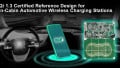
Qi is a wireless power transfer standard developed by the Wireless Power Consortium that specifies an interoperable solution for inductive charging over distances of up to 4 cm. The Qi standard specifies several key features such as operating frequency, coil configuration, minimum system efficiency, power control methods, and communications protocols.
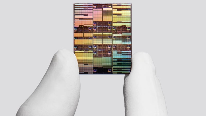
Recently, STMicroelectronics announced a Qi-compliant 50 W wireless charging IC, the STWLC88, that targets applications such as smartphones, tablets, and laptops. The company claims the new device enables safe wireless power delivery nearly as quickly and efficiently as a wired charging solution.

ST says the STWLC88 is the "world's fastest Qi wireless charging IC." Image used courtesy of STMicroelectronics
For safe wireless power delivery, careful attention should be paid to several design challenges such as efficiency, reliable communication, foreign object detection (FOD), thermal considerations, and over-voltage/over-current protection. In this article, we’ll take a look at a few basic concepts of the Qi standard.
Block Diagram of a Qi-Compliant Charger
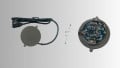
The block diagram of an inductively-coupled wireless power delivery system is shown below:

Functional diagram of a typical wireless power transfer. Image used courtesy of Texas Instruments
The AC voltage applied to the primary coil is transferred to the secondary through magnetic coupling. With the Qi standard, the transmitter and receiver coils should be relatively well-aligned to have efficient power delivery. The magnetic coupling between the coils is also used to send the communication packets from the receiver to the transmitter.
Before power delivery can be performed, several different phases should be completed. Below, we’ll briefly review different steps of the Qi-compliant charging algorithm.
Analog Ping
During standby mode, the transmitter is in the idle state and no appreciable power is output. The transmitter uses “analog pings” to detect the presence of any potential power receiver. Analog pinging is achieved by applying periodic test pulses to the primary coil.
Without a power receiver (and passive metal objects such as coins, keys, etc.), the voltage across the primary coil will be much larger. For example, bringing a power receiver close to the transmitter might reduce the voltage across the primary from 60 Vp-p to 30 Vp-p. This is due to the loading effect that a metal object can have on the primary coil.
Hence, the voltage that appears across the primary during analog pinging can be used to detect the presence of a potential power receiver. Note that some Qi-compliant power transmitters do not use analog pings and rely only on digital pings to detect a power receiver.
Digital Ping
After the transmitter detects a potential power receiver in proximity, it uses “digital pings” to communicate with the receiver. Digital pings are longer pulses compared to analog pings and have sufficient energy to activate the power receiver (if one is present).
Upon being powered by the digital ping signal, the receiver should send signal strength packets back to the transmitter. A valid signal strength packet lets the transmitter distinguish a valid power receiver from a passive metal object or a non-compliant receiver.

Analog and digital pings at startup. Image used courtesy of Texas Instruments
With a valid signal strength packet, the transmitter will maintain power to the coil and proceed to the next phase: the identification and configuration phase.
Identification and Power Transfer Phases
In the identification and configuration phase, the power receiver sends the transmitter data packets that contain information about the Qi version of the receiver, the maximum required output power, and other configuration information.
After the identification phase, the power transfer phase begins. In this phase, the receiver measures the power it receives and sends this information back to the transmitter so that the transmitted power level can be adjusted depending on the receiver requirements. This information also helps the transmitter detect any foreign metal object that steals the power.
Foreign (metal) object detection (FOD) is achieved by comparing the transmitted power with the received power reported by the power receiver. A large difference between the transmitted and received power levels can be an indication of a metal object in close proximity to the transmitter.
Transmitting a large amount of power to a metal object can increase its temperature and cause hazardous situations. That’s why the transmitter will stop supplying power if a foreign metal object is present.
How Does the Transmitter Adjust the Power level?
A typical power transfer function from the LC circuit of the transmitter to the rectifier output of the receiver is shown below.

Graph of a Tx-Rx transfer curve. Image used courtesy of Richtek
In this example, the operating frequency of the transmitter is on the right side of the resonance frequency of the LC circuit. As such, we can reduce the transmitted power level by increasing the frequency of the power signal that is applied to the transmitter coil. The amplitude of the AC signal is another parameter that the system can tweak to adjust the transmitted power.
How Does the Receiver Communicate With the Transmitter?
The magnetic coupling is used for both power delivery and communication purposes. Interestingly, this can be achieved by changing the receiver side load. This RX coil modulation will reflect back to the TX side and allow us to send data packets from the receiver to the transmitter. Capacitive modulation of the RX coil is illustrated below.

The architecture of a 5 W wireless power transfer. Image used courtesy of Texas Instruments
With the Qi standard, both capacitive and resistive modulations of the RX coil are supported.
Do you have hands-on design experience with Qi wireless charging technology? What benefits and challenges have you faced with it? Share your thoughts in the comments below.


I’ve made dozens of transmitters and receivers using mostly Chinese domestic solutions. Not a lot of devices will support 50W with such integration “hardness” and for me, there is more sense to stick with 35-45W max power that is easily available at reasonable costs now.
The last my project I built using MT5725 and that was great: 30W, reverse charging, and super simple and cost-effective circuit.
Does QI wireless charger compatible with iphone 12 series