Facebook
 Google
 GitHub
 Linkedin
New Transceivers Illustrate the Importance of Electrical Fast Transient (EFT) Immunity
Renesas recently released a family of transceivers described as having "the industry's highest EFT immunity." How exactly does an engineer test for and mitigate EFT?
Electrical fast transient (EFT) is a sequence of high-frequency pulses generated by connection, disconnection, and switching-related arching. This event causes damage to electrical systems and devices, such as AC power mains, ethernet and data lines, and automotive DC power systems.
To avoid damaging transients and improve product reliability, designers must test these systems and devices for EFT. This article gives an overview of electrical fast transient, EFT mitigation, and EFT testing, using Renesas’ new high EFT immunity solutions as an example.

Renesas says the RS-485/422 transceiver family has the highest EFT immunity in the industry. Image (modified) used courtesy of Renesas
What Is Electrical Fast Transient?
Relays, heavy-duty motors, switch contactors, and other inductive loads typically generate a series of high-frequency pulses (also known as electrical fast transient (EFT)) on power systems during switching-related arching (or sparking).
This series of pulses exposes electrical systems and equipment to transient-induced noise, resulting in a host of failure modes, including latch-up, reset, communication failure, analog and digital signal corruption, and memory corruption.
To efficiently minimize or eliminate the occurrence of these modes, designers incorporate electronic equipment with high immunity to EFT. These kinds of equipment can withstand and properly function in an electromagnetic environment.
Mitigating Electrical Fast Transient
Some techniques for mitigating EFT noise-related failures in electronic systems and devices include:
- Source-bound transient energy reflection through a least-impedance return path
- EFT energy dissipation
- High transient-induced noise immunity firmware/software
However, designers must apply these mitigation techniques after considering the electronic system levels, power supply and target board designs, and firmware techniques.
The image below shows the various subsystems that make up a conventional electronic system.

Subsystems in an electronic system. Image used courtesy of Cypress
By providing an adequate power supply, designers can minimize EFT in the system. Similarly, an optimized PCB layout boosts the overall EFT immunity of the system. Thus, system design is essential to prevent system failures caused by EFT. Additionally, designers must incorporate properly designed firmware to ensure timely detection, elimination, and recovery of transient-induced errors.
In light of system-level considerations, designers must separate or shield subsystems and their elements from power supplies, ensure isolated cabling and power/signal entry routing, and place on-board connectors at the edge of the board. Thus, the subsystems get enhanced protection from radiated transient-induced noise originating from the power supply area.
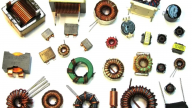
Although most power line filters adequately mitigate low-energy EFTs, the AC and DC power entry points in electronic systems require additional suppression with more effective filters, such as ferrite core-based common-mode chokes.
Designers can also incorporate transient-protection networks into system designs to efficiently handle in-bound transients by limiting voltage, ensuring fast response, limiting/diverting current, and dissipating and withstanding transient energy.
Exploring EFT Testing Setup
Testing for EFT involves subjecting electronic equipment to a series of pulses to confirm its immunity. EFT testing is crucial to ensuring that the equipment under test (EUT) meets compliance and product reliability requirements. Designers typically perform EFT testing on power lines through a coupling/decoupling network (CDN). However, communication, data, and signal lines also require testing.
Engineers commonly test electronic equipment for EFT in line with the International Electrotechnical Commission's IEC61000-4-4 standards. This guideline presents immunity requirements and procedures for electrical and electronic repetitive EFT-based testing. Consequently, engineers select the right testing equipment that meets their needs, in addition to IEC61000-4-4 compliance.
Engineers consider some common factors when conducting EFT testing, including frequency, test voltages, EFT immunity waveforms, and testing equipment setup. In compliance with IEC61000-4-4 guidelines, engineers switch inductive loads and relay contact bounces to generate fast transients and check the level of immunity of the EUT.
The image below shows the various test levels and corresponding test voltage and repetition frequency that engineers consider during EFT testing.

EFT test levels. Image used courtesy of Renesas
A typical EFT test setup includes a ground reference plane, EFT pulse generator, high voltage/current generator, data/communication lines, CDN, insulating support, and connection/grounding cabling. Grounding is essential to the setup since EFT testing depends on fast rise times and high voltages.
Similarly, engineers must also maintain proper connection paths and spacing to meet stringent safety standards during EFT testing. While the EFT or burst pulse generator offers testing capabilities for multiple wave surges, the voltage/current generator adequately meets the EUT power requirements.

EFT test setup. Image used courtesy of Transient Specialists
However, if the voltage and current requirements of the EUT exceed 300 V and 16 A, respectively, the overall test setup may require an external CDN.
Renesas' Solutions With High EFT Immunity
Renesas recently announced the release of its 5V RS-485/422 transceiver family, which offers exceptional EFT immunity for demanding industrial and automation applications.
Since conventional test levels have a maximum corresponding test voltage of 4 kV, Renesas transceivers promise the industry the highest EFT immunity yet, withstanding a high test voltage range of ±5 kV. These devices meet RS-485 and RS-422 communication standards, making them useful for a wide range of applications, including building automation, security cameras, process control, and industrial networking.
Other key features of Renesas' RAA78815x transceiver family include:
- Less than 125 µA bus input currents
- Low supply current of 550 μA
- Shutdown currents of 70 nA
- ESD immunity of ±16 kV
- Small 3 x 5 mm MSOP and 6 x 8.6 mm SOIC package options
- Multiple data rate support
The company achieved a high level of EFT immunity in these devices by incorporating on-chip transient protection circuitry into the transceiver design. Designers can add extra transient voltage suppressors (TVS) to handle surge transients that result from lightning strikes, load changes, or short circuits.