 Facebook
 Google
 GitHub
 Linkedin
Average Power Consumption Monitoring: Maxim’s New Four-Channel Power Accumulator
Maxim Integrated recently announced an SMBus, four-channel average-power monitoring IC.
Maxim Integrated recently announced an SMBus, four-channel average-power monitoring IC.
The MAX34417 allows you to monitor the time-averaged power consumption of four separate devices. Implementation seems to be rather straightforward, especially considering that accumulated power-consumption data is delivered in digital format via an I2C/SMBus interface. Within the datasheet, Maxim has provided nine pages (pages 9–17) related to SMBus operation, slave addressing (we'll touch on this a bit more), and command codes.
The general idea here is that the MAX34417 measures both the current flowing into a circuit (by means of a series resistor) and the voltage across the circuit. It periodically samples these two values and then multiplies them to produce an instantaneous power measurement. These instantaneous power measurements are added to an accumulator value; in other words, they are integrated over time.
The device also keeps track of the number of measurements that have been accumulated. The user reads these two values (according to the desired averaging interval) and then performs a bit of math to determine the average power.
_typical_application.jpg)
MAX34417 block diagram, from the datasheet (PDF).
It’s a simple scheme, but you have to keep in mind that the accumulation register cannot accumulate forever. It’s 56 bits wide, which means that it can hold a very very big number, but the power measurements are 30 bits wide and they’re accumulated 1024 times per second, so reading the accumulated value is not something that you can do once per week or even once per day (the datasheet indicates that the 56-bit register can hold about four and a half hours of data).
Offered in Rather Small Package
Initially, given the power monitoring capabilities of this device, I was expecting this IC to come in a large, or at least larger, package. But it turns out that this four-channel power monitor is available in a 2 × 2 mm WLP with 16 bumps at a pitch of 0.4 mm (see the image below). So, if you're planning to hand-place this part, you’d better have a very steady hand, or a very capable electronics technician (or brain surgeon) available.
_pinout.jpg)
This IC is available only in a small wafer-level package with 16 bumps. Image taken from the datasheet (PDF).
Setting the IC's SMBus Slave Address
This IC includes only a single slave-address setting pin (ADDR), and thus it is surprising to learn that a total of eight slave addresses are available...using this one pin! The chip is able to support eight addresses because the ADDR pin can detect specific address voltage values—called slicing voltages—that are created using ±1% tolerance resistors.
While I do understand the concept being used here, I have never seen this approach before, and the voltage range associated with each address seems somewhat tight. Consequently, I'm wondering how reliable this address-selection scheme is.
Have you seen this technique used in other ICs, and do you have experience with it, specifically in terms of reliability? If so, please share your experience in the comments section below.
_slave_address.jpg)
This table from the datasheet explains how the single ADDR pin uses multiple voltage ranges for determining the IC's slave address.
Voltage Sequencing Not Required
You may have noticed, in the block diagram above, that this IC uses three input voltage types: the INxP and INxN voltages, the VIO voltage, and the VDD (or VCC) voltage.
_input_voltage_types.jpg)
Fortunately, complicated voltage sequencing is not required, and you can safely apply voltage to one of the inputs without applying voltage to the other two inputs. For more information on this topic, check out the Pin Description table on page 8 of the datasheet.
Average Power Calculation Example
Within the Applications Information section of the datasheet (page 18), Maxim describes a fairly straightforward three-step process for calculating average power based on the IC’s accumulated power value, the accumulation count, and the “correction factor” corresponding to the value of the current-sense resistor (see the two figures below).
It probably goes without saying, but still... the current-sense resistor values in the table should be in units of milliohms ("mΩ") and not megaohms ("MΩ").
_application_example.jpg)
Calculating the average power looks to be fairly simple. From the datasheet (PDF).
_resistor_correction_table.jpg)
This correction factor table is used when calculating average power. Note that the current-sense resistor value unit should be "mΩ" (milliohms). From the datasheet (PDF).
An Evaluation Kit Is Available
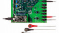
If you're interested in taking some average power accumulation measurements without designing a new PCB, there is the MAX34417 evaluation kit available. In addition to the hardware (see image below), this kit includes a graphical user interface (GUI) that helps you to evaluate the MAX34417 and streamline your development efforts.
_eval_board.jpg)
The MAX34417 evaluation and development board. Image taken from the evaluation kit's user guide (PDF).
Have you had a chance to use this new four-channel power-consumption monitor or the evaluation kit? If so, leave a comment and tell us about your experiences.


Nick,
Great article! You did well highlighting main points about the MAX34417 and gave your readers a clear, high-level, pragmatic perspective about the product itself as well as the accompanying EV Kit. Superb read.
Thank you so much .Very useful article..I did my controller based arduino training in inplant training .
Thank you so much .Very useful article..I did my controller based arduino training in inplant training .