Facebook
 Google
 GitHub
 Linkedin
Rohde & Schwarz Releases New Oscilloscope Tool Designed to Decompose Jitter
Why is jitter becoming an increasingly difficult problem to solve? Rohde & Schwarz helps designers respond to these challenges with a jitter analysis tool.
What is Jitter?
Jitter, in laymen terms, is randomness in signal frequency whereby a signal source, such as a 1 kHz square wave, will not always be at 1 kHz. Some portions of the waveform will be higher than 1 kHz and others will lower than 1 kHz.
This variance in frequency, which changes with time, has its own frequency and alterations in the waveform. Those that occur at a rate greater than 10 Hz are called jitter whereas those under 10 Hz are referred to as wander. But when does jitter become a problem and what applications are most at risk?
Jitter in Communication and DSP
Generally speaking, communication links are those most prone to jitter problems. This is because these applications must transmit data that is synchronized to a clock source. Other applications, including digital signal processors, can also experience jitter.
Why does a circuit suffer from jitter and what should designers look out for? Simply put, major issues with jitter arise when the variance in a clock signal interferes with data transmission timing.
If, for example, a UART port operates at 300 baud and its reference clock source is a 64 MHz crystal, then the variance from the crystal is so small (parts per million) that even the most extreme signal variance of the 64 MHz will have little effect on the 300 baud signal.
If a 300 baud UART port derives its timing from a clock source whose variance caused a UART frequency shift of 10 Hz, then suddenly the baud rate (which is now changing by ±3%) becomes significant enough that data on the receiving end can be misinterpreted.
So, to summarise, jitter becomes a problem when variance in the frequency of the signal is significant enough to adversely affect the timing of data. Jitter doesn’t affect data rates because of a change in frequency; the changing frequency causes the data on the receiving end to be misinterpreted.
Rohde & Schwarz Jitter Decomposition
When determining the jitter of a system, an analysis tool that generates eye diagrams can provide great insight into the amount of jitter in a circuit and determine a safe area of operation. However, determining jitter is only the first step. The type of jitter also needs to be determined. From there, designers can figure out how to identify sources of jitter and rectify the issue if needed.
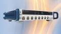
Rohde & Schwarz is responding to this conversation on jitter with its newly announced tool, RTO/RTP-K133, that will be included in their oscilloscope products.

RTO/RTP-K133. Image used courtesy of Rohde & Schwarz
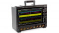
The jitter tool not only produces the eye diagram for a signal but also separates the jitter into its individual components. These include random jitter, data-dependent jitter, and periodic jitter.
Using this analysis, a designer can determine if jitter is the result of random variations in the circuit or if it is due to the interference from components when data is transmitted.

Inferface for RTO/RTP-K133. Screenshot used courtesy of Rohde & Schwarz
What also makes the R&S RTO-/ RTP-K133 tool unique is that it performs the test on the complete characteristic of the waveform under test, unlike other standard tests that only perform time interval error measurements.
Other Jitter Inspection Tools
Jitter tools are not only limited to one or two specialized oscilloscopes. Designers can find these tools from many different manufacturers. For instance, in the past, we've discussed how Rigol released an oscilloscope in 2019 called the MSO8000, which includes jitter analysis in real-time with a bandwidth of up to 2 GHz. It also produces eye diagrams.
Keysight, another company based around signal analysis, also produces jitter measuring tools. For instance, their sampling oscilloscope, the 86100C DCA-J, can perform jitter analysis between 50 Mbps to over 40 Gbps. The device, highly sensitive to intrinsic jitter, conveys jitter types and offers multiple views on the jitter data.
What makes the Rohde & Schwarz tool different is that it is incorporated into standard bench oscilloscopes whereas the Keysight 86100C DCA-J is a specialized tool.
Conclusion
While it's clear that jitter can be highly problematic in environments with high-speed data connections, jitter can also be a problem in other digital circuitry. The ability to measure it can provide insight into the quality of a signal and the amount of noise present.
Being able to differentiate the type of jitter can drastically reduce debug time by helping to identify which components in a circuit are causing the jitter.