Facebook
 Google
 GitHub
 Linkedin
Custom Microcontroller Design: Hardware, Tools, and Toolchain
This is Part 1 of a step-by-step guide to bringing custom microcontroller designs to life.
This is Part 1 of a step-by-step guide to bringing your custom microcontroller design to life.
Related Information:
- Choosing the Right Oscillator for Your Microcontroller
- Custom PCB Design with an EFM8 Microcontroller
Most electronics enthusiasts eventually reach a point at which it would be beneficial to design a custom PCB that includes a microcontroller. This path leads away from the convenience, proven functionality, and development support provided by evaluation boards. These features are helpful, to be sure, but they also prevent us from gaining the deeper insight that results from custom design. With a custom board, you will have to design these features on your own. In addition, you have to test them and confirm that everything is working as expected.
Microcontroller Hardware—What do we need?
A custom microcontroller design doesn't need much additional circuitry to come to life. All it needs is the following:
- some sort of power supply
- a hardware interface for connecting your flash or debug tools
- a clock
- a reset circuit

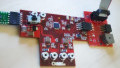
A minimal setup for a microcontroller
Power Supply
As with every electrical circuit, we need a reliable power supply. You must create a power supply circuit that accepts the range of expected input voltages and provides all supply voltages that the microcontroller needs.
Please don't forget to include a decoupling (aka bypass) capacitor for each VCC pin—this applies to the microcontroller as well as all other integrated circuits on the board. The typical value is 100 nF, but always check the device's datasheet just in case it provides specific decoupling recommendations.
Clock
The clock is the heartbeat of the microcontroller. Without a heartbeat, a microcontroller can't do anything. It simply won't run.
Many microcontrollers include an internal clock source, and this is usually the best option if you don't need a highly stable or highly precise clock frequency. When high stability or precision is needed, a common choice is a crystal-based oscillator.
Consider the following factors as you carefully choose the right clock source:
- the desired frequency
- the frequency tolerance from part to part
- jitter, i.e., cycle-to-cycle variation in the period of the oscillating signal
- stability of frequency over temperature
- package
- load capacitance (you generally need to include external load capacitors when using a crystal)
Also, you have to check the microcontroller's datasheet regarding the default clock configuration. The microcontroller cannot boot up without an acceptable clock for its initial configuration processes.
Reset
The microcontroller has a reset pin, and you need to be careful with the circuitry attached to this pin. This might sound strange—maybe you're thinking, "It's just a pull-up or pull-down resistor!"
But it's not always that simple. The reset pin allows you to restart your microcontroller without cycling power or connecting your debug tools. The reset pin could be driven by a pushbutton or another device on the board, or it could even be connected through a cable to an external controller of some kind. In any event, you need to make sure that the circuit driving the reset pin provides an appropriate reset signal (usually active-low, and watch out for switch bounce if you're using a pushbutton).
The other concern is spurious resets. These can occur if the reset pin is left floating or if the pull-up resistor is very large (because this makes the reset line more sensitive to noise). And even if your pull-up resistor is not too large, you still have to consider the possibility of spurious resets caused by noise coupling in from nearby traces or from sources of high-intensity EMI (electromagnetic interference).
Hardware Interface for Flash or Debug Tools
You need a physical connector on your custom design in order to connect your flash/debug hardware. This can often be a basic pin header to which you connect your flash/debug hardware. The only things you'll need to know are the interface standard (JTAG, SWD, ISP, DebugWire, etc.) and the proper pinout for your programmer hardware. Actually, you may need to know very little about the actual debug interface—often the best approach is to simply duplicate the microcontroller-to-debug-header connections shown in the schematic for a relevant evaluation board.
At this point we have covered the essential portions of a microcontroller design. If you have all this circuitry in place, you should be able to load a program into your microcontroller so that it can start doing something rather than nothing.

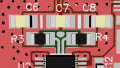
An example of 10-pin and 6-pin pinouts for in-system programming (ISP) headers. Image courtesy of osiixy (own work) [CC BY 3.0]
Tools and Toolchain—What Do We Need?
The vast majority of modern evaluation boards (Arduinos, for example) come with a fully integrated USB interface and a preinstalled bootloader. Just plug the board into a USB port, install the proper driver for your OS, maybe select a COM port, and press the programming button in your IDE. It is that easy.
You may need a little more external hardware and a little more know-how to get a custom microcontroller design up and running.
So let's assume the following: Your microcontroller doesn't have a bootloader in its memory and your custom PCB doesn't include flash/debug hardware.
Flash/Debug Interface Hardware (Including Drivers)
There are plenty of suppliers of flash/debug hardware tools, which range from very cheap to very expensive.
Keep in mind that not all flash/debug hardware has drivers for all operating systems. Also, not all drivers are easy to install. Take your time and make sure that you are purchasing the right device for your microcontroller design.

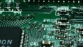
An example of a flash/debug interface device. Image courtesy of Segger.
Initial Firmware Testing
For initial testing of the microcontroller, you need some basic firmware. A classic blinking-LED program is fine, or you can come up with any other straightforward functionality that provides clear confirmation that your microcontroller is actually executing the firmware. If your board does not have an LED or any other indicator, you can generate a square wave on one of the pins and confirm that the signal is present using an oscilloscope.

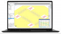
Integrated development environment (IDE) software allows you to create a program and load it into the microcontroller's flash memory. Image courtesy of ARM Inc.
Programming Tool
You need a programming software tool in order to load your program file into your microcontroller's flash memory. Usually you will use the programming functionality that is incorporated into the integrated development environment (IDE) that you use to write your firmware.

The programming tool included in Atmel Studio. Image courtesy of Atmel.
Working with Your Custom Microcontroller Design
So let's say that today you received your first custom design from your favorite PCB manufacturer. Let's bring this baby to life!
Check the Empty PCB
First of all, check the empty PCB to see if there is anything obviously wrong. That might sound silly, but I've seen completely mirrored PCBs and PCBs with shifted solder masks. You need to be on the lookout for issues caused by the manufacturer and not by the designer. Usually the PCB will be fine—actually, if you are using a reputable manufacturer it is extremely unlikely that the board will have any serious issues. Nevertheless, you all know Murphy's law.
After checking for obvious problems, open up your CAD software and take a few minutes to compare the actual PCB to the layout file. If you find some errors on the PCB which are not your fault, don't hesitate to send a complaint to the manufacturer. It is better to find any imperfections now rather than after you have all the components soldered to the board.
Shorts and Opens
Most PCB manufacturers can do an electrical test (aka e-test) to confirm that all the connections in the actual PCB are consistent with the connections in the CAD data. This may even be included in the standard price. If you don't have your boards e-tested (or if you have doubts about the quality of the e-test), you can either assume that the boards are functional or check the connections yourself using a multimeter.
What's Next?
It's time to fire up your soldering iron and gather all the parts that you will need for your custom microcontroller design!
In the next article, I will give you some step-by-step advice on how to assemble, solder, and test your PCB, and we'll also cover how to load firmware into the microcontroller's flash memory.