Facebook
 Google
 GitHub
 Linkedin
Custom Microcontroller Design: Assembling, Measuring, Programming
This is part 2 of a step-by-step guide to bringing your custom microcontroller design to life.
This is part 2 of a step-by-step guide to bringing your custom microcontroller design to life. We'll cover assembly, initial measurements, and programming.
Related Information:
Piece by Piece: Assembling, Soldering, and Testing
Begin by preparing everything you need for assembly and soldering on your desk. Keep in mind that you don't want to assemble and solder all the parts onto your first prototype PCB and then do all the testing. It's better to solder just a functional subsection of your circuit—the power supply, for example—and then confirm that this subsection does what it is supposed to do. Then solder the next functional subsection and test it, and so on.
This step-by-step approach to soldering and testing will help you to identify the source of any problems that arise. Also, you might be able to find a design error before it causes damage to another component (e.g., it is better to discover that your power supply is generating 5 V instead of 3.3 V before you apply that voltage to your microcontroller).
Solder the power supply circuit and test it
In general, the first subsection that you should solder is the power supply circuit. After soldering the power supply circuit, clean it up with a proper cleaner for PCBs (e.g., isopropyl alcohol) and check it for short circuits and open circuits. (At this point we're assuming that the PCB has no manufacturing defects, so in this context short and open circuits are soldering defects.)
Take your laboratory power supply, set an appropriate current limit, and power your partly assembled PCB. Now measure with your multimeter all the output voltages that your circuit creates, and to be extra careful you can confirm that the correct voltage is present at all of the microcontroller's supply pins. Then don't forget to turn the power off before you proceed.
Solder the microcontroller circuit
Now that the power supply circuit works, we can assemble the microcontroller circuit.
First, solder the microcontroller and the passive components used for filtering the supply voltages (decoupling capacitors are always required, and in some cases ferrite beads are beneficial). Be sure that your microcontroller is placed with the right orientation. You can now use your multimeter to check for shorts and opens, but if you want to test the microcontroller's functionality you need to solder the clock source (unless the microcontroller has an internal oscillator), the reset circuit, and any components required for your flash/debug hardware.
When you have everything soldered, clean it up with your preferred cleaner. Do a visual inspection (a microscope or magnifying glass is helpful here, especially with fine-pitch components), and use your multimeter to check any connections that you are concerned about. As shown in the following diagram, you can use the multimeter's resistance-measuring feature to assess your solder connections.

Be especially careful with all power supply connections (don't forget that the debug header might have power pins). An open circuit here could render your microcontroller completely nonfunctional, and a short circuit could lead to damage.
At this point your PCB has minimal active circuitry and the microcontroller has no firmware, so there shouldn't be a large current draw when you power up your board. If you haven't already, adjust the output voltage and the current limit of your bench supply, then switch on the power and see what happens. If, contrary to expectations, the bench supply's display indicates high current, switch it off again. Don't panic (easier said than done); just take out your multimeter and magnifying glass and try to track down the problem.
Check the voltage at the reset pin
To ensure reliable operation, the reset pin must have a stable, clean voltage that is well within the logic-high or logic-low specifications in the microcontroller's datasheet. If the reset pin is active-low, you need a logic-high voltage to enable the microcontroller; if it is active-high, you need a logic-low voltage.
If the microcontroller has an internal pull-up (or pull-down) resistor on the reset pin and you have no need for hardware reset functionality, you might have no additional circuitry connected to the reset pin. In this case there is no need to check the voltage at the reset pin. But if your design includes a reset circuit, measure the voltage at the reset pin to ensure that it is acceptable.
Probing the clock
This step is not necessary if you are using an internally generated clock signal (though at some point you may want to measure the internal clock to determine its exact frequency). For external clocks, it's a good idea to look at the signal using an oscilloscope.
First of all, it's not always easy to obtain an accurate representation of the clock signal. This is especially true when the oscillator is a crystal connected directly to the microcontroller—the probe introduces impedance that can cause the oscillation frequency to shift, and in extreme cases the circuit can stop oscillating when the probe is applied. A better way to precisely measure the frequency when using a crystal is to enable the microcontroller's clock-output functionality and then probe the digital signal (but of course you can't enable clock output until you are able to load a program into flash).
If the oscillator signal is buffered, as with a crystal oscillator module or a silicon oscillator, you can probe the output of the oscillator device without affecting the frequency.
Even with a crystal, though, you should be able to get fairly accurate measurements without too much difficulty. Make sure you are using a 10:1 probe; the additional capacitance associated with a 1:1 probe is likely to interfere with the circuit.
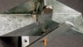
When you probe one of the crystal pins, you should see a sinusoidal signal with frequency approximately equal to the crystal's specified frequency, as shown in the following scope capture.

Probing the clock—measuring an 8 MHz signal from a quartz crystal
Connecting the flash/debug adapter to your custom design
Now we can move on to connecting the flash/debug hardware. Please make sure to disconnect the power before continuing.
The flash/debug adapter will have some way of making a connection between the adapter and the connector on your PCB. Usually there will be a cable, but maybe all you will have is individual wires. Also, there may be multiple connectors on the adapter. Confirm that you are using the right connector for your programming interface standard, and double-check that the connections on your PCB match the pinout on the flash/debug connector. Eventually, though, the double-checking has to end; at this point you just plug in the debug cable, power up the PCB, and hope nothing burns.

Example of a flash/debug adapter with two connector options. Image courtesy of Atmel.
The flash/debug adapter will usually have status LEDs that give you some sort of information about what is happening inside—e.g., the device is powered but idle, programming is in process, the microcontroller is executing code in debug mode. The following image gives you an example of flash/debug status LEDs.

Status LEDs on a JTAG ICE (in-circuit emulator) device. Image courtesy of Atmel.
Establish a connection between your PC and your custom microcontroller design
Open the programming tool or IDE (integrated development environment) and configure your flash/debug adapter. Then, try to establish a connection to the microcontroller. The programming tool or IDE will tell you if it worked or not.
If it doesn't work, check your connections again. If the connections look right and you can't find any other obvious problem, don't despair. Look around for information on how to properly configure the software for your specific connection circumstances. Also, it's helpful if you have an evaluation board for a microcontroller that is the same as or very similar to the one on your custom PCB. If you can't connect to the eval board, then the problem might be in the debug adapter or the PC software rather than your PCB.
But let's assume that everything is going well and you can connect to your microcontroller with no problems. Now you are able to load your own firmware into the microcontroller and modify the hardware configuration. Be careful, though, and make sure you are familiar with the microcontroller's low-level functionality (as explained in the datasheet). Things can quickly go awry if you fiddle with the wrong configuration bits or download seriously dysfunctional code. In the worst-case scenario, you can lock yourself out of your microcontroller.
Configure the clock
One of the most important configuration options is the clock. The microcontroller's default clock configuration might not be the one you want. If you are using an 8-bit ATmega (PDF), for example, it will be configured to use a 1 MHz internal RC (resistor-capacitor) oscillator by default. If you want a different frequency or a different clock source, you need to modify the hardware configuration settings. This can be done by incorporating the necessary register modifications into your firmware, and nowadays the IDE will probably include a tool that greatly simplifies the process of generating hardware-configuration code.
As mentioned in the previous section, be careful when making changes! Your microcontroller will not be happy if, for example, you (accidentally) tell it to use an external clock signal that doesn't exist.
Download your first program
We've come a long way, and now it's time to load a program into your microcontroller's flash memory. Start with something simple, and if possible incorporate some basic visual feedback (e.g., a blinking LED). If you don't have an LED, just toggle an output pin and check it with a scope. All you're trying to do at this point is confirm that the code is successfully downloading and executing.
Before you download your test program, look for options corresponding to "erase," "program," and "verify." Selecting these options means that three things will happen when you click the download button:
- The microcontroller's program memory will be erased.
- The object file corresponding to your code will be transferred to the microcontroller and stored in the nonvolatile program memory.
- The PC software will read back the data in the program memory to verify that no errors were introduced during transmission or during the process of writing the object file into flash.
If the download procedure is successful, execute the program. This can be done through the IDE's debugging functionality or by resetting the microcontroller. (The most surefire way to perform a reset is to close the connection between the PC and the microcontroller, remove the flash/debug cable, and then power cycle the board.) If your test program works, congratulations! Your custom PCB—or at least the microcontroller portion of the PCB—is working properly.
Assemble the rest of your design
At this point, close the flash/debug connection, remove the cable, and power down your PCB. Now you can solder the remaining parts, test your other circuits, and gradually implement all the necessary firmware functionality.
Conclusion
Designing your first custom microcontroller-based PCB can be challenging. It's worth it, though.
Remember to take everything step by step, and don't get discouraged when things don't initially work as expected. You can either fix or come up with a workaround for many problems that arise during the assembly and testing phase. And if you really botched something, use the first version of the board as a coaster or paperweight and go back to your CAD software. That is a mistake you won't make twice, and maybe you have already noticed a few other improvements that can be incorporated into the second version.
But if you're careful with your schematic and layout work and you double-check every critical aspect of the design, chances are you'll be rewarded with an awesome custom PCB that does what you need it to.