 Facebook
 Google
 GitHub
 Linkedin
Breadboarding and Programming the ATmega328P & ATtiny45 in Atmel Studio 7
In this project, we'll build circuits for programming two different Atmel microcontrollers and we'll discuss the necessary software setup.
In this project, we'll build circuits for programming two different Atmel microcontrollers and we'll discuss the necessary software setup.
This project will describe the construction of two very similar circuits: one for programming an ATmega328P and another for programming an ATtiny45. The article will provide a complete schematic diagram of the programming circuits as well as detailed photographs of the solderless breadboard assemblies. In addition, Atmel Studio 7 IDE (Integrated Development Environment) will also be introduced.
First, the Hardware
The ATmega328P is a 28-pin microcontroller from Atmel and is part of the AVR line. It is probably best known as the most frequently used μC in the Arduino brand of development platforms, but the AT328P is capable of much more than can be squeezed from it there. If you want to see some evidence for that statement, have a look at the 660-page datasheet.
The ATtiny45 is an 8-pin μC and might be thought of as the “baby brother” of the ATmega328P. It has many of the same features, but of course it does not have nearly as many I/O pins.
The Serial Peripheral Interface (SPI) is used for programming the ATmega328P and the ATtiny45; it is a three-wire (plus ground) bus, consisting of a Master Out, Slave In (MOSI) signal, a Master In, Slave Out (MISO) signal, and a Serial Clock (SCK) signal. The clock is generated by the master device and is used to ensure synchronized communication between the master and the slave (or slaves); therefore, SPI is a “synchronous” communication bus.
Programming Circuits
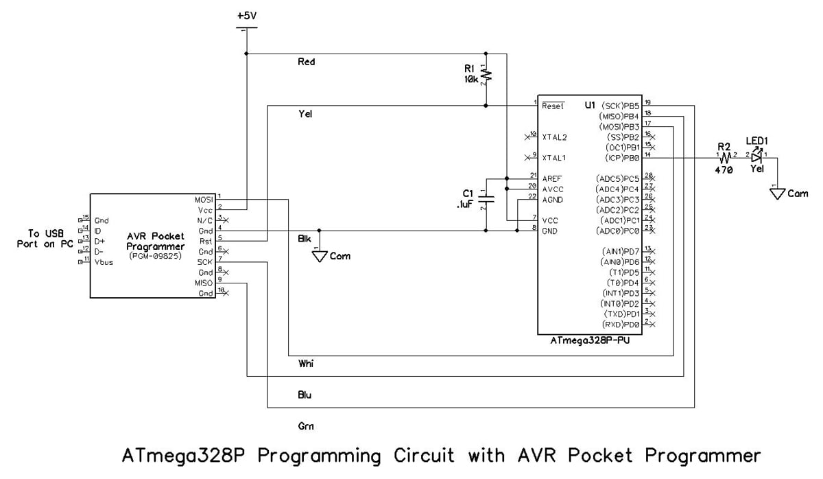
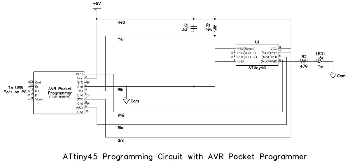
The schematic diagrams for the programming circuits are shown below. Note that resistor R2 and LED1 are not strictly required for programming but are included in the circuit for testing purposes as defined later in this project.
Programmer Choices
Several programmers are available that will handle the ATmega328P and the ATtiny45; the Atmel-ICE is at the top of the list, and is a fine programmer that will be discussed in a future article. For now, there are less expensive options available to the skinflints among you, and the Sparkfun AVR Pocket Programmer is the one used by the skinflint author of this article. If you prefer something else, feel free to pick the one that suits your preferences and your pocketbook. Just be sure that it uses the Serial Peripheral Interface as previously described, and be prepared to make the appropriate changes to the information in this article.
CAUTION! Be sure to download and install the appropriate driver for the AVR Pocket Programmer on your computer before you plug the programmer in for the first time. If Windows is allowed to install the wrong driver, it can be very problematic to correct. Instructions for obtaining the AVR Pocket Programmer driver are provided later in this article.
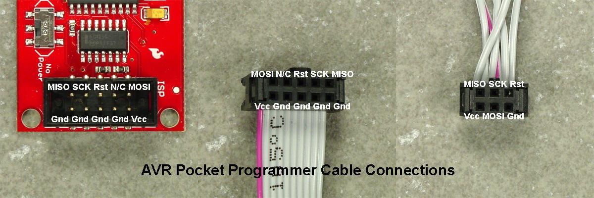
The AVR Pocket Programmer comes with a ribbon cable that is to be connected to the Atmel μC. It is fitted with three connectors: a 2×5 female that is plugged into the mating male header on the AVR Pocket Programmer, another 2×5 female that is about 9 inches (23 cm) down the ribbon cable (that is not used in this article), plus a 2×3 female at the end of the ribbon cable. The pinouts are shown in the photographs below.
Programming Circuit Solderless Breadboard Assemblies
The ATmega328P and ATtiny45 programming circuit solderless breadboard assemblies are shown in the following photographs. Six short jumper wires are used to connect the required leads from the 2×3 female connector to the appropriate pins on the microcontroller in the solderless breadboard. Note that the wire colors in the assembly photographs below correspond to those in the schematic diagrams above.


Parts List
In addition to some wire jumpers, the parts required for the programming circuit assemblies are listed in the following table.
| Part Ref. | Description | Source | Item No. |
|---|---|---|---|
| U1 | IC, ATmega328P-PU, 32kB Flash, DIP-28, 1.8-5.5V | Digi-Key | ATMEGA328P-PU-ND |
| U1 | IC, ATtiny45-PU, 4kB Flash, DIP-8, 2.7-5.5V | Digi-Key | ATTINY45-20PU-ND |
| R1 | Resistor, ¼ W, 10kΩ | Digi-Key | 10KQBK-ND |
| R2 | Resistor, ¼ W, 470Ω | Digi-Key | 470QBK-ND |
| LED1 | Diode, Light Emitting, T1 3/4, Yellow | Digi-Key | 754-1889-ND |
| C1 | Capacitor, Ceramic, 0.1µF, 50V | Digi-Key | 399-9797-ND |
| N/A | Programmer, AVR Pocket, PGM-09825 | Digi-Key | 1568-1080-ND |
| N/A | Breadboard, Solderless, 400 Contact | Digi-Key | 377-2094-ND |
Then, the Software
AVR Pocket Programmer Driver
The Windows driver for the AVR Pocket Programmer is the same one that is used by the Adafruit USBTiny Programmer. Go to this Adafruit web page and click on the link for the Windows USBtinyISP signed driver built with libusb v1.12. That will allow you to download a zip file that contains two installer.exe files: one for 32-bit computers and one for 64-bit computers. Double-click on whichever one is appropriate for your Windows PC, and the driver will be installed.
Only after installing the correct Windows driver should you connect the AVR Pocket Programmer to your computer for the first time. You will need a USB Type A to Miniature B male-to-male cable to connect from your PC to the AVR Pocket Programmer. When you make the connections, the blue PWR LED and the red Stat1 LED should light up; the two blue data LEDs may also light up and/or flicker. Windows will attempt to locate the driver, and you should direct Windows to the correct driver’s location as necessary. Once properly installed, the AVR Pocket Programmer will show up in Device Manager under libusb-winXX devices as “USBtiny”; it will not be enumerated as a COM port. See the screenshot below:

Atmel Studio 7
Like many microcontroller design firms, Atmel has an Integrated Development Environment (IDE) that works with their hardware offerings: Atmel Studio 7. Although it’s not the only way to program Atmel μCs, it is the most fully featured method for Windows 7, 8, and 10 (both 32-bit and 64-bit); unfortunately, it can’t be used with Linux or Mac operating systems.
The number of options and choices in Atmel Studio 7 can be overwhelming for a new user. Thus, a step-by-step approach will be provided in this project, and will greatly simplify the process. Begin by downloading and installing the IDE on your PC. The Studio 7 User Guide and a wealth of additional information are also available to download.
Support for several hardware programmers is included in Studio 7, but the exact choices depend upon which Atmel microcontroller you are going to use. In the screenshot below, the programmers that are supported for the ATMega328P are listed on the right.

As you can see, the AVR Pocket Programmer is not on the list. However, it can still be used with Studio 7 with the help of a piece of software called AVRDude.
AVRDude
AVRDude is a command-line utility that is used to download from and upload to Atmel microcontrollers. Versions are available for both Linux and Windows systems. As of this writing (7 June 2017), the latest version available is 6.3; it can be downloaded here. Windows users should download avrdude-6.3-mingw32-zip (clicking this link will download the zip file!), unzip the files, and install AVRDude. Note that installing the program in the root of your main hard drive is not essential but will simplify its use with Atmel Studio 7. If a version later than 6.3 is available, you may decide to install it at your discretion. The user guide for AVRDude is available here.
To check whether AVRDude is properly installed and working, take the following steps:
- Click the Windows Start button.
- In the search box, type cmd and press Enter. A DOS prompt window should open.
- At the DOS prompt, change to the directory where you installed AVRDude.
- Type avrdude -c USBtiny and press Enter. If all is well, AVRDude will return a list of Atmel devices that are supported.
See the screenshot below for an example of the procedure. Note that the screenshot has been truncated and shows only part of the list of supported Atmel devices.

Putting It All Together
Assuming the programmer is connected to the AVR on your solderless breadboard as previously described, you are almost ready to program your AVR. Download the file New Blink.zip using the button below, unzip it, and save it on your PC in a convenient location.
Now, follow this procedure.
- Start Atmel Studio 7.
- At the left of the startup screen, click New Project. The New Project screen will open.

- At the New Project screen, click GCC C Executable Project; name the project New Blink as shown above, and click OK. The Device Selection screen will open.

- At the Device Selection screen, choose the AVR device you are using: ATmega328P or ATtiny45 as shown below. Click OK. The new project will be created and the New Blink project screen will open.

- Click the Tools pulldown menu, choose External Tools…, and click the Add button.
- In the Title box, type a name for the tool you are creating; it’s good if the name is descriptive of the tool. For example, you might enter a combination of the programmer name and the device name.
- In the Command box, type the DOS address for the location where you installed AVRDude plus the command to start AVRDude.
- In the Arguments box, type one of the two following lines depending on which AVR you are using. For the ATmega328P, type:
-c usbtiny -p m328p -v -U flash:w:$(TargetDir)$(TargetName).hex:i
For the ATtiny45, type:
-c usbtiny -p t45 -v -U flash:w:$(TargetDir)$(TargetName).hex:i
- In the Initial directory box, type the DOS address for the location where you installed AVRDude.
- Be sure the Use Output window box is checked and the other two check boxes are not checked. The window should be similar to the screen below, but reflecting the AVR you are using.

- Click Apply and then click OK. The External Tools window should close.
- Go to the location where you unzipped and stored New Blink.c at the beginning of this section, open the file, select all the contents, and copy it to the clipboard.
- Go to the New Blink.c window in Atmel Studio 7, select all the contents, and paste the contents of the clipboard into the New Blink.c window. It should appear as shown below.

- If the Atmel Studio 7 Solution Explorer is not open at the top right of the project window, click the View pull-down menu, and click Solution Explorer. The Solution Explorer should open at the top right of the project window.
- Right click on the main.c file and choose rename. Rename the main.c file to New Blink.c.
- Click the File pull-down menu, and click Save All.
- Click the Build pull-down menu, and click Build Solution.
- Click the Tools pull-down menu, and click the name of the tool created in steps 5 through 11 above. The compiled New Blink code should be downloaded to the AVR in your breadboard, and LED 1 should begin flashing: on for ½ second and off for ½ second, 60 times per minute.
The Beginning
Admittedly, that was a long process for just flashing an LED, but the truth is that you have successfully cleared four major hurdles: creating a hardware platform for programming an AVR microcontroller, installing an integrated development environment (Atmel Studio 7), integrating an external program (AVRDude), and defining a programming tool for the AVR of your choice. Rest assured it will get easier for future Atmel projects that are a lot more fun. Watch for them at AllAboutCircuits.com.
Give this project a try for yourself! Get the BOM.


hey Charles R. Hampton i am facing some problem while burning AVR can you please share your mail-ID so i can clearly elaborate you problem..
I am very interested in moving beyond the limitations of the arduino IDE.
Hope this turns into a comprehensive series