 Facebook
 Google
 GitHub
 Linkedin
Build a Wireless “Tipping Bucket” Rain Gauge, Part 1—Assembling the Bucket
A tipping bucket rain gauge, an RF transmitter and receiver, a PICAXE microcontroller, and an LCD can make a great addition to your weather station.
Pump up your weather station with a tipping bucket rain gauge, an RF transmitter and receiver, a PICAXE microcontroller, and an LCD.
Overview
This is the first article in a three-part series that describes the construction of a "tipping bucket" rain gauge with a wireless connection to a PICAXE-controlled LCD (liquid crystal display.)
Part 1 focuses on the mechanical construction of the tipping bucket mechanism.
Part 2 describes the modification and use of an RF (radio frequency) transmitter that sends rainfall collection indications.
Part 3 describes the RF receiver that receives the signals and the PICAXE 08M2 microcontroller that interprets the signals and displays the rainfall data on the LCD.

Click to enlarge.
The completed outdoor assembly is shown in the following photograph.

As you can see, the collection device is a plastic funnel which channels the rainwater into a small section of aluminum downspout that houses the actual tipping bucket mechanism.
As the bucket tips, electrical signals are routed through the green wires to the RF transmitter contained in a weatherproof plastic case. The RF transmitter and a 9-volt battery are inside the case, and the antenna is the grey wire that exits from the bottom.
Now we can move on to the mechanical and construction details.
The Tipping Bucket
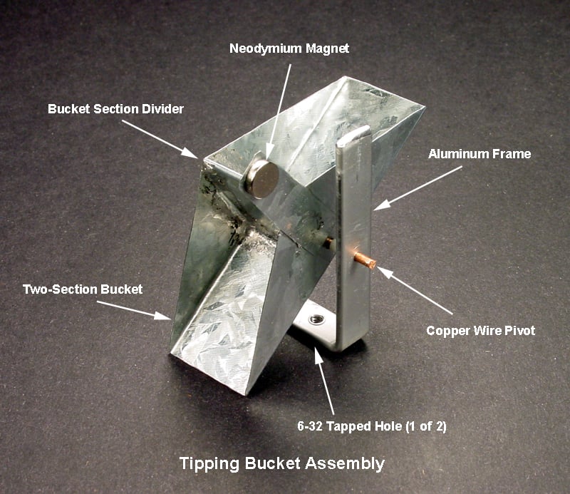
As shown in the photo below, the tipping bucket doesn't look much like an ordinary bucket. It consists of two triangular receptacles on opposite sides of a center divider; the entire assembly pivots on an axle that runs through its lower section. As water drips into the raised receptacle, it collects until its weight causes the assembly to pivot, which dumps the water from that receptacle and positions the other receptacle to catch the water.
When that receptacle fills, the assembly pivots again, which dumps the water and starts the sequence over. The filling, pivoting, and dumping continues for as long as rainwater drips into the receptacles. Each time the assembly pivots, the magnet is moved in an arc from one side to the other.
Click to enlarge.
"What good does that do?" you might ask. And the answer is "none"—until a means is provided to detect the magnet's movement.
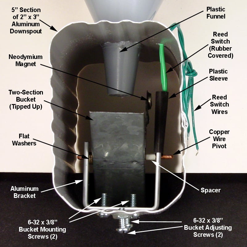
Consider the photo below. On the right side, a reed switch is held in place on the aluminum bracket by the black plastic sleeve. The green wires connect the reed switch to the RF transmitter circuit, which supplies a low DC voltage to one wire and watches for that voltage on the other wire. Thus, each time a receptacle fills with water and the bucket assembly pivots, the magnet passes the reed switch, which causes the switch to close and the RF transmitter to send a short signal.
Note that the reed switch and the wire connections are encased in rubber to prevent water from accessing the connections and to provide protection to the fragile reed switch.
Click to enlarge.
There are two details shown in the photo that are easily overlooked:
- Every effort is made to minimize friction between the tipping bucket and the pivot axle. The bucket is loose between the two vertical arms of the aluminum bracket. Washers and a spacer (made from the copper wire insulation) help to center the bucket under the funnel spout without pinching the bucket. In addition, the only points of contact between the bucket assembly and the pivot axle are where the pivot axle passes through each side of the bucket assembly.
- Two bucket adjusting screws are provided, one under each end of the bucket. These are used to adjust the tipping point for each receptacle, and ensure that both sides contain the same amount of water when they tip.
Parts List
The parts list below is for this article, the first in a series of three; each article includes its own parts list.
The list includes some items which you may already have in your junk box or parts bin, or that you can scrounge. For example, you might find some galvanized flashing remnants or 12-2 Romex scraps at a construction site. Likewise, the aluminum bar for the tipping bucket frame in the photos came from a junked flatbed scanner.
It is important to not use ferrous metals for the overall housing or the bucket frame. Using non-ferrous components in these areas will minimize interference with the magnetic field operating the reed switch.
| Part | Details | Source | Item # |
|---|---|---|---|
| 3" x 5" Aluminum Downspout Extension | Amerimax 27075 | Lowe's | 27075 |
|
8" x 1' Galvanized Steel Sheet Flashing |
Amerimax 70981 | Lowe's | 125854 |
| 3' x 3/4" x .016" Aluminum Bar | Hillman 11288 | Lowe's | 24403 |
| 12-2 Insulated Copper House Wire (15' roll) | Romex 28828226 | Lowe's | 302631 |
| 6-32 x 3/8 Machine Screws and Nuts (14 pack) | Hillman 491279 | Lowe's | 57818 |
| 3.5" Top Diameter Plastic Funnel | Blitz 05007 or Hopkins 49742 (3-pack) | Lowe's | 05068 |
| Neodymium Magnet (10 Piece Set) | 1 Magnet Needed | Harbor Freight | 67488 |
| Washers, #4 | 2-5 Needed | A/R | N/A |
Tipping Bucket Construction
Layout
The bucket depicted in this article was constructed from 32 gauge galvanized flashing; 30 gauge would also work. This material has several benefits: it is easy to cut with cheap kitchen shears, it is easy to bend into the required shapes, it is rust resistant, and it is solderable with ordinary equipment.
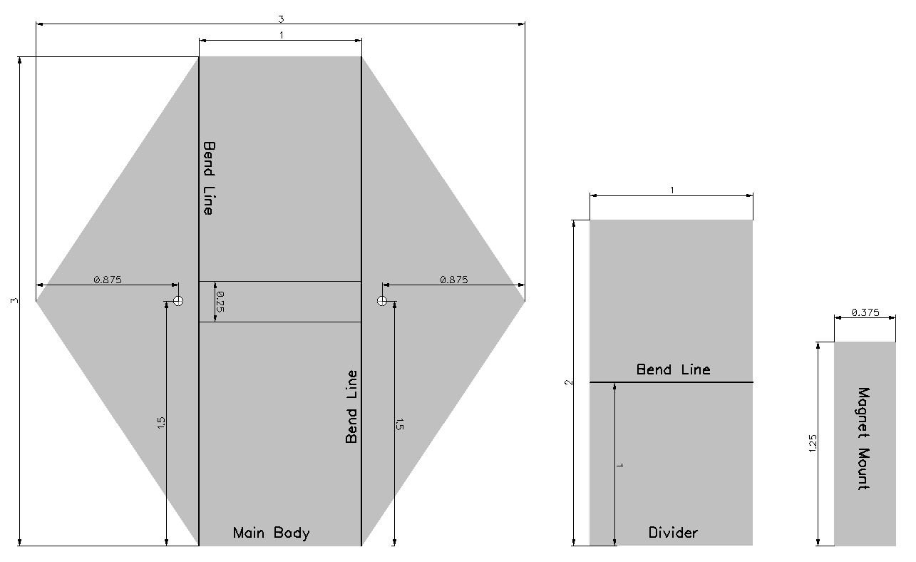
The drawing below shows the three pieces of metal required for the bucket construction: the main body, the divider, and the mount for the neodymium magnet. All dimensions are in inches.
Click to enlarge.
The tools required for laying out and cutting the bucket pieces from 32 gauge flashing are shown in the photo below.

Follow these steps to measure, drill, and cut your flashing pieces:
- Use a factory edge on the sheet metal to establish a base line. Starting from there, scribe lines to form a square, 3 inches on each side. Mark the sheet metal with the awl; it will be easy to see the lines and the awl is easy to move precisely against the steel rule.
- On two opposing sides of the 3-inch square, mark the midpoints at 1.5 inches. On the other two opposing sides, mark 1 inch from both sides.
- Connect these six points with lines to form the outline for the main body of the bucket.
- Scribe the two fold lines and the two short lines near the center to identify where the divider is to be placed.
- Mark the centers for the two axle pivot holes by using the tip of the awl and tapping lightly on the butt of the handle, and then drill the holes with a 3/32" drill bit.
- Use the shears to cut out the six-sided main body of the bucket.
- Repeat the same general process for the two smaller sheet metal pieces.
Bending
Bending the two 3-inch lines in the main body of the bucket is easily done by using a small scrap of metal or hardwood with a well-defined corner along one edge.
Place one of the bend lines directly over the corner and start the bend by hand. Once the bend is started, continue to force the metal to conform to the 90º corner of the block. A small vise and mallet can be helpful. Repeat the process with the other bend line in the main body.
When you have the main body in the U-shape required, check the fit of the divider between the two sides. It should be a close fit, but doesn't have to be perfect. You may need to snip off tiny amounts from the corners of the divider in order for it to fit well in the inside bends of the main body.
Next, bend the divider along the scribed line, but don't bend both halves of the divider flat. Instead, leave a gap of approximately 1/4 inch between the open ends of the divider. This will result in the divider being slightly "tent shaped," and will leave room for the axle pivot to pass between the divider halves without touching them.
Reference the two lines on the center area of the main body to see where the open ends of the divider should be placed.
Attaching the Sheet Metal Parts
At this point, you are almost ready to start attaching the divider to the main body of the bucket. Soldering is the preferred method, but epoxy could also be used.
Whichever method you choose, dry fit the parts thoroughly to be sure that the mating surfaces join smoothly with minimal gaps and no bulges. Then, fasten the parts with small clamps and begin soldering or glueing. Soldering is easily done with 60/40 or 63/37 solder, and a good iron with a 1/8" bevel tip at about 750°F (400°C).
Start at the bottom edge of the divider, first on one side and then on the other. Next work up the four sides in turn, finishing at the bend line at the top of the divider. Once all the seams are soldered, you can go back over them one at a time to smooth out the rougher surfaces.
Whether you use solder or epoxy, the seams should be waterproof, but they don't have to be cosmetically perfect. Small differences in the capacity of the two bucket receptacles can be compensated for by using the adjustment screws.
Tipping Bucket Assembly
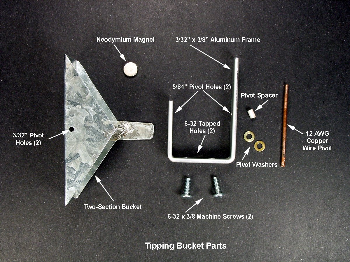
The photo below shows the parts for the tipping bucket assembly.
Click to enlarge.
The exact dimensions of the aluminum frame and copper pivot are dependent upon the dimensions of your bucket and are not precision parts. However, the following notes should be of value as you collect and fabricate the parts:
- The Neodymium magnet is about 5/16 inch in diameter. During the preliminary assembly, the magnet will hold itself in place on the metal mount. After its optimum placement is determined, it should be epoxied in place.
- One side of the aluminum frame is longer than the other in order to provide a mounting location for the reed switch.
- The 12 AWG copper wire pivot will be a force fit through the 5/64 inch holes in the aluminum frame.
- The brass pivot washers and the pivot spacer are used to center the tipping bucket assembly in the frame. The pivot spacer is made from a small piece of plastic insulation from the 12 AWG wire. Use as many brass pivot washers as required to provide a close, but non-binding fit of the bucket assembly in the frame.
- The 3/32 inch pivot holes will provide for a close, but non-binding fit on the 12 AWG copper wire pivot.
- The 6-32 tapped holes and 6-32 machine screws will be used to attach the completed tipping bucket assembly inside the 5-inch length of aluminum downspout.
Installing the Tipping Bucket Assembly and Funnel
The Tipping Bucket Assembly
When the tipping bucket assembly is complete, it should be installed in the center of the 5-inch section of the 2 inch x 3 inch aluminum downspout. Refer to the last photograph in "The Tipping Bucket" section above.
The following steps describe how to install the tipping bucket:
- Place the tipping bucket assembly inside the downspout near the center; make sure that there is adequate clearance on the top and the two sides. Remove the bucket assembly and mark and drill two clearance holes for the 6-32 mounting screws in the center of the downspout. The holes should be spaced the same distance apart as the two drilled-and-tapped holes in the aluminum frame.
- Mount the tipping bucket assembly inside the downspout. Tip the bucket mechanism to one side and note where the edge of the bucket contacts the bottom of the downspout. Mark and drill a clearance hole for a 6-32 machine screw.
- On the outside bottom of the downspout, sand and/or scrape away the paint for about 1/4 inch around the clearance hole you just drilled. Epoxy a 6-32 nut centered over the hole; this will allow for the insertion of a machine screw to serve as a bucket adjustment screw for this side. Repeat the process on the opposite side of the bucket.
- Next, drill a 3/16 inch hole in the top corner of the downspout; this hole should be centered from end to end in the downspout. The hole is for entry of the wires for the reed switch, but neither the reed switch or the wires should be installed at this time.
.jpg)
Click to enlarge.
The Funnel
The recommended plastic funnel is a 1/2 pint model that is approximately 4 1/4 inches tall with a 3 1/2 inch top opening. It is marketed in the United States under a variety of brand names including Blitz, model 05007. That is the funnel shown in the photographs in this article.
Whatever plastic funnel you use, cut a hole in the top center of the downspout just large enough for the spout of the funnel to enter the downspout. Make sure that the funnel spout is not so long that it will interfere with the tipping action of the bucket.
Note that leaving the edge of the hole slightly ragged will help to retain the funnel in the hole. When you insert the funnel into the hole, twist it as you press down on it; this technique will actually allow the rough edges of the hole to cut "threads" into the surface of the funnel. Do not try to seal the funnel in the hole at this point.
Next Time
If you are thinking there wasn't much electronics information in this article, you are correct! But that will change in the next article in the series.
Part 2 will introduce the RF transmitter and receiver. It will show you how to modify the transmitter, install it in a weatherproof case, connect the reed switch, power it up, and test it.
Happy building!
Next Article in Series: Part 2—Adding the Transmitter


Perhaps you could have made the hole for the reed switch at a position lower than where said switch will be, so as to avoid water entering with the wire and rusting the soldered connection, or make a loop so that water can fall from the cable. Remember that when you have different materials soldered together, the oxidation reaction is much quicker!