 Facebook
 Google
 GitHub
 Linkedin
Build a Wireless “Tipping Bucket” Rain Gauge, Part 2—Adding the Transmitter
A tipping bucket rain gauge is a clever way to measure rainfall. Learn how to add wireless capability, a PICAXE microcontroller, and an LCD display to your weather station.
A tipping bucket rain gauge is a clever way to measure rainfall. Learn how to add wireless capability, a PICAXE microcontroller, and an LCD display to your weather station.
Overview
This article is part 2 in a series of three detailing the construction of a tipping bucket rain gauge. Part 1 described the mechanical construction of the tipping bucket itself as well as the housing for the bucket; if you have not read part 1, you should do so before reading this article.
Part 2 will present the electrical connections, the remaining required parts for the outdoor assembly, and the instructions for the transmitter portion of the wireless controls.
Part 3 will focus on the receiver, the PICAXE microcontroller, and the LCD (liquid crystal display) that will be used to show the rain data results.

Click to enlarge.
The best-laid schematics o' mice an' men...
If you are paying close attention, you may have noticed that the diagram above has changed since it appeared in part 1. A new functional block has been added to the outdoor assembly: a pulse stretcher. Here's why.
The original plan for this project was that a magnet attached to the tipping bucket would operate a reed switch, which would trigger a transmitter. The transmitter would send a pulse to a receiver where the pulse would be presented to a microcontroller, which would record the pulse and use it to calculate and display rainfall data.
And it worked...part of the time. As it turns out, the bucket tipping action was too fast; the pulses were always recognized by the reed switch, and the transmitter was always activated, but often the receiver was too slow to receive the short RF (radio-frequency) pulse.
What was needed was a longer RF pulse from the transmitter, but the operating mode of the transmitter was to transmit a pulse for only as long as a button was held down. And because this design uses a reed switch instead of a manual pushbutton, the RF pulse length was totally dependent on the length of time it took the magnet to pass the reed switch.
However, the world's most popular IC will provide the solution: a 555 timer circuit set up as a monostable multivibrator—better known as a "one-shot." There is a hitch, however. The NE555N is somewhat of a power hog, and given that the chip would have to be idling continually 24/7 waiting for input from the reed switch, the 9-volt battery wouldn't last long.
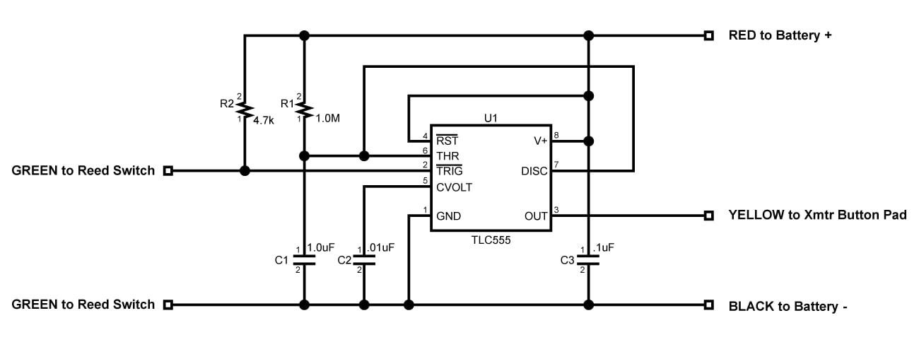
Fortunately, a CMOS (complementary metal–oxide–semiconductor) version of the 555 is available which draws very little standby power: a TLC555 from Texas Instruments was put into service in the circuit shown below.

Click to enlarge.
In operation, when the magnet passes the reed switch, a low-going pulse is presented at the trigger input (pin 2) of the 555. The 555 then generates a positive pulse at its output (pin 3) for approximately 1.1 seconds (length determined by R1 and C1.) The transmitter turns on for 1.1 seconds, and the receiver has plenty of time to lock in on the signal and notify the microcontroller.
And in case you are wondering, the circuit draws only about 150 µA in standby mode, and approximately 27 mA while it's transmitting, which means that the 9-volt battery should have a good life expectancy.
Problem solved!
Parts List
This article is the second in a series of three; each article includes its own parts list. Assuming you have completed construction of the tipping bucket mechanism and housing as described in part 1, you are ready for the parts in the following table.
| Part | Details | Source | Item # |
|---|---|---|---|
| Reed Switch | Standex-Meder Electronics ORD211-1015 | Digi-Key | 374-1083-ND |
| Wire, Insulated, Stranded, 24 or 26 AWG | Green, Red, Black, and Yellow Needed | A/R | N/A |
| Liquid Tape | Gardner Bender LTB-400 (Black) | Lowe's | 118455 |
| Transmitter (Key Fob) & Receiver Modules, 315 MHz | 1 Each Needed | On-line, Off-shore | N/A |
| Perfboard | 1 Needed: 1 Inch x 3/4 Inch | A/R | N/A |
| Timer IC, CMOS, TLC555 | 1 Needed | Digi-Key | 296-1857-5-ND |
| Capacitor, Ceramic, 50V, 1.0µF | 1 Needed | Jameco | 81509 |
| Capacitor, Ceramic, 50V, .1µF | 1 Needed | Digi-Key | BC1160CT-ND |
| Capacitor, Ceramic, 50V, .01µF | 1 Needed | Digi-Key | BC1078CT-ND |
| Resistor, .25W, 1M ohm | 1 Needed | Digi-Key | 1.0MQBK-ND |
| Resistor, .25W, 4.7k ohm | 1 Needed | Digi-Key | 4.7KQBK-ND |
| Battery Clip | 1 Needed | Jameco | 109154 |
| Wire, Insulated, Solid, 22 AWG | 9 Inches Needed | A/R | N/A |
| Case, Plastic, Waterproof, 85 x 58 x 33mm | 1 Needed, with Gasket and Cover | On-line, Off-shore | G1CG |
| Tape, Foam, Double-sided | 2 Pieces Needed, 1/2 Inch x 1/2 Inch | A/R | N/A |
| Battery, 9-Volt | 1 Needed, Alkaline Preferred | A/R | N/A |
| Sleeve, Plastic, 2 Inches Long, Internal Dimensions to Fit Bucket Frame | 1 Needed | A/R | N/A |
| Glue, Epoxy | Small Amount Needed | A/R | N/A |
| Sealant, Silicone | Loctite 2.7 Oz. Waterproof Sealant | Lowe's | 908570 |
Reed Switch Connections
As previously described, the tipping action of the bucket during the collection of rainfall will cause a neodymium magnet to move back and forth. In order to detect this movement and control an electrical signal, a reed switch is used. The reed switch in the construction project for this article is shown in the photograph below. This switch is quite small and fragile, and you are advised to have a few spares. Other reed switches with similar performance characteristics can be substituted.

The reed switch contains a pair of contacts inside a glass enclosure. The contacts are normally open (NO) until they are acted upon by a magnetic field such as the one that is created by the neodymium magnet. Thus, as the magnet passes the reed switch, the contacts close, and as a result a low-going voltage signal is applied to the pulse stretcher circuit. This occurs once each time the bucket tips from one side to the other.
Because bending the leads on the switch can cause fracturing of the glass enclosure, the following method of attaching the wires is recommended.
Strip about 1/2 inch of insulation from the ends of two 8-inch pieces of insulated 24 or 26 AWG stranded wire. Gently twist one stripped wire end around each of the reed switch leads (with as little bending of the reed switch leads as possible) and solder the connections. Paint some liquid tape over the switch leads and soldered wire joints. When dry, the liquid tape will provide electrical insulation, add water resistance, and supply mechanical protection to the switch.

For more information about reed switches, check out the training modules at Digi-Key.
Transmitter and Receiver Modules
No transmissions of complex data are required in this project. In fact, all that is required is that each tip of the bucket results in a single pulse being sent from the outdoor assembly to the indoor assembly. As a result, a simple garage door opener radio-frequency system is a good choice. Although this project uses a four-channel system, a single channel is all that is required.

This transmitter and receiver pair operates at 315 MHz. To operate it manually, the user extends the transmitter antenna and presses one of the ABCD buttons on the keyfob. The transmitter inside the keyfob sends a corresponding RF signal and lights the LED on the keyfob for as long as any one of the four buttons is held down.
While the signal is received, a logic high is placed on the pin extending from the bottom of the receiver that corresponds to the button pressed; the logic high lasts for as long as the transmitter button is held down.
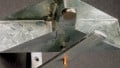
There are at least two variants of this remote control system, shown in the photographs below.

The main differences in the transmitters are (1) the old models have surface mount pushbutton switches while the new models use through-hole switches, (2) the old models include a model 23A, 12V battery but the new ones do not, and (3) the positive and negative battery terminals are reversed. The models seem to be functionally equivalent.

The layout of the receiver PCBs is completely different from the old to the new, however, they seem to be functionally equivalent. Using old and new style receivers and transmitters together causes no problems.
Modify the Transmitter
An old version of the transmitter was used for this article but with minor changes in the process, a new version may be used instead; use whichever you have.
- Remove the transmitter from the case.
- Desolder and remove one of the pushbuttons from the PCB. The PCB seems to be of good quality, but take care not to peel up or burn the traces. It doesn't really matter which button you remove since you will be able to accommodate your decision when wiring the receiver section.
- Next, scrape away some of the green solder resist from the button's lower trace and tin the exposed portion of the trace as shown below.

- Desolder and remove the telescoping antenna from the transmitter; remove the solder from the antenna mounting hole.
- Desolder and remove the battery connectors from the transmitter; remove the solder from the mounting holes.
Build the "Pulse Stretcher" on Perfboard
There are only six electronic parts in the pulse stretcher: a TLC555 IC (integrated circuit,) a 1.0µF ceramic capacitor, a 0.1µF ceramic capacitor, a .01µF ceramic capacitor, a 1M ohm .25 watt resistor, and a 4.7k ohm .25 watt resistor.
In addition, five lengths of insulated 24 or 26 AWG stranded wire need to be connected: two 2-inch lengths of green wire, one 4-inch length of yellow wire, one 5-inch length each of black and red wire. Finally, you will need a piece of perfboard no larger than 1 inch by 3/4 inch in order to mount the components.
A photo of the pulse stretcher built for this article is shown below. Yours will look different due to the perfboard you use and the layout you choose.

Follow the schematic/wiring diagram shown below exactly to build your pulse stretcher.
Click to enlarge.
Build the "Pulse Stretcher" on a PCB
If you would rather build the pulse stretcher on a printed circuit board, that's possible as well. The same six electronic parts and the same five lengths of stranded wire are required as listed above, but instead of a piece of perfboard, use a PCB as shown in the photograph below.
In the image below, a fully populated board is on the left, the top layer of a bare board is in the center, and the bottom layer of a bare board is on the right. These three boards were ordered from BasicPCB for a total of $9, including shipping. The PCB layout was done in DipTrace; those files and the required Gerber files are available for downloading at the end of this section.

For those of you who prefer to "roll your own" PCBs, representations of the top and bottom layers of the layout are shown in the two drawings below. Note that the bottom layer is intentionally reversed. The exact size of the finished PCB should be 1 inch wide by .7 inches high.


Make the Connections
A step by step approach to wiring the subassemblies together is recommended.
- Orient the subassemblies as shown in the photo below, then solder the red and black wires from the pulse stretcher board and the red and black wires from the battery connector to the transmitter board. Don't forget that the polarity of the power connections to the transmitter is reversed on the new-style transmitter board as compared to the old-style transmitter board. On the old models, the negative is on the right as shown in the photograph below; on the new models, the negative is on the left.
- Solder the yellow wire from the output of the pulse stretcher board to the tinned pad on the transmitter board as shown.
- Solder a 9-inch length of insulated 22 AWG solid wire to the antenna terminal on the transmitter board; orient the wire as shown in the photograph.
- Note that the two green wires to the reed switch are shown with a female Dupont connector, which is optional.
2.jpg)
- Place a 1/2-inch by 1/2-inch piece of double-sided foam tape on the rear of the pulse stretcher board, and a similar piece on the rear of the transmitter board. Do not remove the protective paper from the foam tape on either board at this time.
Fill the Case
This procedure uses a waterproof plastic case, preferably with a clear plastic top; the case shown in the photograph below was used in this article. Its outside dimensions are approximately 85 mm (3 1/4 inches) wide, 58 mm (2 1/4 inches) high, and 33 mm (1 1/4 inches) deep; it is available from both domestic and overseas sources. The case includes a rubber gasket to seal out water and mounting ears on the sides for easy attachment to a flat surface.

- Mount the weatherproof case to the 5-inch long piece of aluminum downspout on the same side as the hole that you drilled for the reed switch wires. Note that the tipping bucket mechanism must be mounted such that the arm holding the neodymium magnet is on the same side as the hole in the downspout for the reed switch wires. Use the mounting ear holes in the weatherproof case as a template to locate the holes to be drilled in the aluminum downspout. Mark and drill two clearance holes for 6-32 machine screws. Attach the weatherproof case to the aluminum downspout using two 6-32 x 3/8 machine screws and two nuts.
- Temporarily place the transmitter PCB in the case as shown in the photo below. Locate and mark the location in the bottom of the case for a 3/16 inch hole for the reed switch wires, and a 1/16 inch hole for the antenna wire. Drill both holes.
- Remove the paper backing from the foam tape on the transmitter PCB, feed the antenna wire through the 1/16 inch hole, and stick the transmitter PCB in the location shown.
- Next, locate the pulse stretcher board as shown on the left side of the case. When you are sure that it is in a location that will not interfere with the seating of the case top, remove the paper backing from the foam tape and stick the stretcher board in the location shown.
- Neaten up the wires and locate them as shown.

- Route the wires from the reed switch through the 3/16 inch hole in the bottom of the case and connect the reed switch wires to the two wires from the transmitter PCB. Use Dupont connectors as shown or just solder the wires and, keeping the joints isolated from one another, paint each solder joint with liquid tape; polarity doesn't matter. Then, position the connections inside the weatherproof case. Note that the holes around the wires in the bottom of the case are not to be sealed. Instead, they are left open to drain condensation from the inside of the case.
- Snap the connector on the terminals of the 9-volt battery, wrap the battery in waterproof padding, and position it as shown in the photograph below. (Note that the transmitter LED should be visible; it is helpful when testing the assembly.) Fit the gasket in the corresponding recess in the weatherproof case and secure the top with the four screws provided.

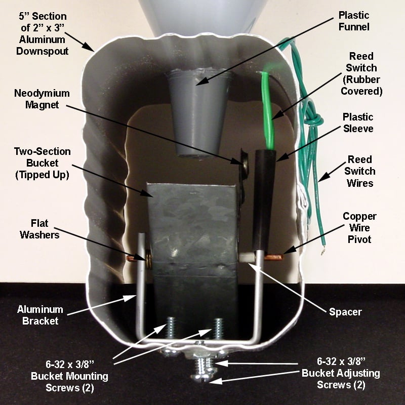
Mount the Reed Switch
Referring to the photo below, insert the reed switch through the hole in the top corner of the aluminum downspout. Place the switch in a vertical position aligned with the longer arm of the bucket frame.
In the assembly shown in the photo below, the end of the reed switch is held loosely in the proper position with a piece of plastic sleeving, which works well. Other options include taping or tying the switch to the arm of the bucket frame. Use whatever method works best for your situation, but don't forget that the glass enclosure of the reed switch is easily broken.
Test and Seal
Test the assembly by manually rocking the bucket from one side to the other; the bucket should move very easily with no noticeable binding at any point in the rocking arc. As the magnet passes through the vertical position, the red LED on the transmitter PCB should light and stay lit for a minimum of about one second. The LED should not be lit when the bucket is at rest at either end of the rocking arc.
Make whatever adjustments are required to the mechanical bucket assembly, the wiring, the exact location of the neodymium magnet, and/or the reed switch until the operation is correct and totally dependable. Then, and only then, should you epoxy the magnet in position, seal the reed switch wire hole with silicone sealant, and apply silicone sealant around the entrance of the funnel into the piece of aluminum downspout.
Take a Break!
At this point, you have a complete weatherproof outdoor rain gauge and transmitter that is totally ready to send signals to your indoor receiver and display. Spend a few minutes enjoying the good feeling of a job well done.
Part 3 defines the breadboarding of the receiver circuit and the programming of the PICAXE 08M2 microcontroller.
Next Article in Series: Part 3—Receiver, PICAXE, and LCD
Give this project a try for yourself! Get the BOM.


Hello!
I’m not an electronician but I want to build a rain gauge with a tipping bucket with an arduino GSM. I can see that I can use your mechanical construction of thé rain gauge (part 1), but I dont know where I could the two green wires linked to the magnet on my arduino shield GSM un order to count the oscillations of the bucket ans sens it may be by SMS via arduino shield GSM.
In another hand, do you think there is a way to change your radio staff by a device un order to sens the measured rain by SMS?
Thanks
Hi,
Thank you for this great project write up.
I’m hitting a snag with the pulse-stretcher: it worked great on the breadboard, but the C1 capacitor won’t charge when mounted on the PCB. Oddly, it works fine when I have my voltmeter on it when a pulse occurs. I looked up the design around the TLC555, and it seems to be the recommended setup. I’m at a loss. Any ideas ?
Thx