Facebook
 Google
 GitHub
 Linkedin
A Dual 38W Power Amplifier: A Compact STA540-Based Stereo Audio Board
This project brief describes how to build a compact dual-channel power amplifier module that delivers 38 W per channel into 4-ohm speakers using STMicroelectronics' STA540 audio amplifier IC.
The design does not require a bootstrap capacitor or a Boucherot network, which keeps the external parts count low. An internally fixed gain of 20 dB sets the amplification stage without external gain-setting resistors. A standby function also lets the board be powered down into a low-current state without removing the main supply.
Power, audio, and speaker connections are all made through screw terminals, so the board can be wired into an enclosure without soldering. A power LED (D1) driven from the supply rail confirms that VCC is present. The STA540 itself includes a set of protection and diagnostic features: a clip detector, short-circuit detection at turn-on, a thermal shutdown warning, and AC/DC output short-circuit protection. Figure 1 shows the assembled board.
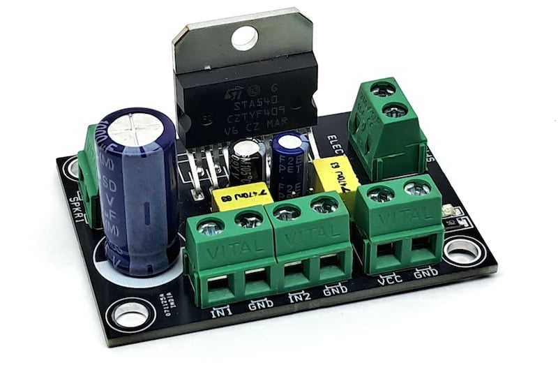
Figure 1. The assembled Dual 38W Power Amplifier board, built around the STA540.
Specs and Features
- Supply voltage: 18 V DC (22 V DC for 8-ohm loads)
- Load impedance: 4 ohms (2 channels)
- Key IC: STA540, 4-channel Class-AB audio power amplifier
- Fixed internal gain: 20 dB, no external gain-setting network required
- THD: 10% at 1 kHz
- Short-circuit output current: 4 A
- AC/DC output short-circuit protection
- Soft short-circuit check at turn-on
- Thermal cutoff / limiter to prevent chip overheating
- CMOS-compatible standby function, no audible pop on standby transitions
- PCB dimensions: 53.34 mm x 38.10 mm
- PCB mounting holes: 4 x 4 mm
How It Works
The STA540 is a 4-channel, Class-AB audio amplifier built around four internal operational amplifier stages (A1 through A4), each driving one of the IC's four outputs. On this board the four internal channels are paired to form two bridged, single-ended output pairs (OUT1/OUT2 and OUT3/OUT4), each feeding one of the two speaker terminals, LS1 and LS2. Audio is applied differentially through IN1/IN2 and IN3/IN4. These inputs are coupled through the 470 nF film capacitors C3 and C6 from the CN2 and CN4 input headers.
The standby pin (ST-BY) is pulled through R1 and switched through CN3. This lets an external 5 V signal put the amplifier into a low-power state without disconnecting VCC. Because the STA540 needs no external bootstrap or Boucherot components to drive its outputs, only a few parts remain: C1, C2, C4, C5, and the LED current-limiting resistor R2. Together, these support supply filtering, soft-start, and the power-present indicator.
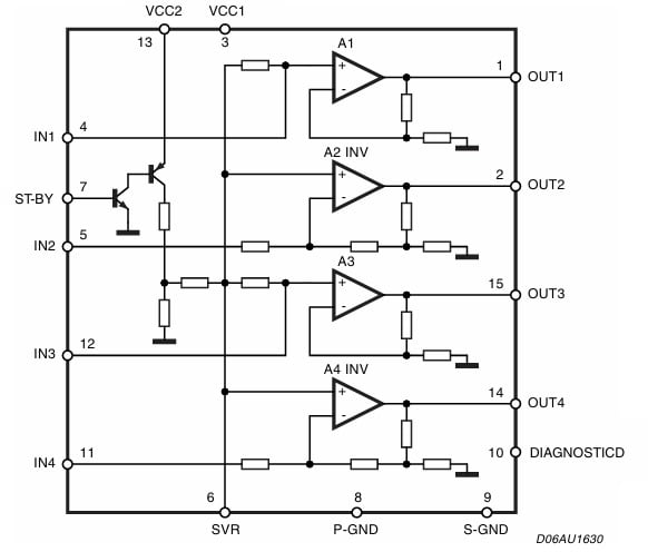
Figure 2. Internal block diagram of the STA540 showing the four amplifier channels and the standby switching transistor. Image used courtesy of STMicroelectronics.
Schematic and Bill of Materials
The full schematic for the Dual 38W Power Amplifier is shown in Figure 3.
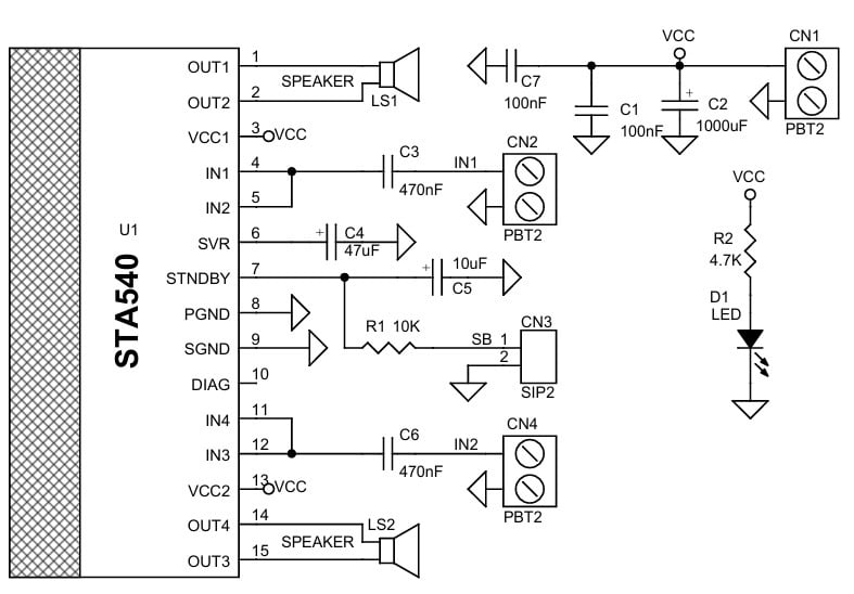
Figure 3. Schematic of the Dual 38W Power Amplifier board.
The bill of materials is shown in Table 1.
Table 1. BOM for the Dual 38W Power Amplifier.
| REF | DESCRIPTION | QTY | MFG | SUPPLIER | PART NO. |
| CN1, CN2, CN4 | 2 Pin Screw Terminals, Pitch 5.08 mm | 3 | Phoenix | Digikey | 277-1247-ND |
| CN3 | 2 Pin Male Header, Pitch 2.54 mm | 1 | Wurth | Digikey | 732-5315-ND |
| C1, C7 | 100 nF / 50 V Ceramic, SMD 0805 | 2 | Yageo/Murata | Digikey |
|
| C2 | 1000 uF / 35 V Electrolytic, dia. 12 mm | 1 | Nichicon | Digikey |
|
| C3, C6 | 470 nF / 63 V Film Capacitor, THT 5x7 mm | 2 | Vishay/Epcos | Digikey |
|
| C4 | 47 uF / 35 V Electrolytic, THT 5x11 mm | 1 | Nichicon | Digikey |
|
| C5 | 10 uF / 63 V Electrolytic, THT 5x11 mm | 1 | Nichicon | Digikey |
|
| D1 | LED, SMD 0805 | 1 | Osram | Digikey | 475-1278-1-ND |
| LS1, LS2 | 2 Pin Screw Terminals, Pitch 5.08 mm | 2 | Phoenix | Digikey | 277-1247-ND |
| R1 | 10 K, 5%, SMD 1206 | 1 | Yageo/Murata | Digikey |
|
| R2 | 4.7 K, 5%, SMD 1206 | 1 | Yageo/Murata | Digikey |
|
| U1 | STA540 | 1 | ST | Digikey | 497-8880-5-ND |
Connections
Figure 4 shows how power, audio, and speakers connect to the board.
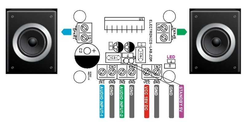
Figure 4. Connection diagram for the Dual 38W Power Amplifier board.
CN1 — Power Input (2-pin, 5.08 mm pitch):
- Pin 1 = VCC
- Pin 2 = GND
CN2 — Audio Input 1 (2-pin, 5.08 mm pitch):
- Pin 1 = Audio Input 1
- Pin 2 = GND
CN3 — Standby Control (2-pin header, 2.54 mm pitch):
- Pin 1 = Standby Signal Input
- Pin 2 = GND
CN4 — Audio Input 2 (2-pin, 5.08 mm pitch):
- Pin 1 = Audio Input 2
- Pin 2 = GND
LS1 / LS2 — Speaker Outputs (2-pin, 5.08 mm pitch):
- LS1: Pin 1 = Speaker 1, Pin 2 = Speaker 1
- LS2: Pin 1 = Speaker 2, Pin 2 = Speaker 2
D1 — Power LED:
- Illuminates when supply voltage is present
PCB Files
The PCB measures 53.34 mm x 38.10 mm. The silk screen, top layer, and bottom layer are shown in Figure 5.
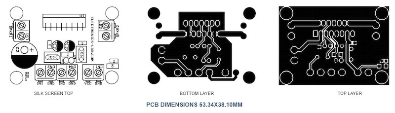
Figure 5. PCB layout for the Dual 38W Power Amplifier, showing silk screen, top layer, and bottom layer.
You can download the layout files for this project here:
38W Dual Audio Power Amplifier Gerber Files
Except where noted, all images used courtesy of Rajkumar Sharma