Facebook
 Google
 GitHub
 Linkedin
Solar Splash: How We Designed a Solar Powered Boat
A detailed look at the solar/electric boat that the University of Rochester Solar Splash team built for Solar Splash.
Get an inside look at the University of Rochester Solar Splash team's competition-grade solar/electric boat.
I recently wrote an article that served as an overview of Solar Splash event as a whole. However, I thought it wouldn’t do justice to the work I, my teammates, and the other teams put in if I didn’t provide a full view of what’s going on ‘under the hood’ in these solar/electric boats. I hope to provide just that, without requiring you to read through a 50-page technical report.

Boat Design
Hull
Designing a good hull is one of the most crucial aspects of building any kind of boat. While there are many modeling programs such as Abacus to help test for hydrodynamic and aerodynamic properties, they nearly always have some level of inaccuracy.
A lot depends on the smoothness of the surface of the hull touching the water. Of course, it is also necessary to have a hull which will be stable in the water. Here are some notes from last year’s tech report documenting its construction and design:
2014-2015 Hull Mold (Multiple Use):
This hull design was machined from two pounds of weight-extruded polystyrene (EPS) foam by Foamlinx LLC (Sunnyvale, CA).
A 3D model was made and sent as an STP (a universal 3D format) to a CNC foam router to get an exact copy of the design. The EPS foam was then coated in Industrial Polymers compound Styropoxy 7060-1 and sanded multiple times until the bodylines were smooth.
The exterior of the mold was coated with Meguiars Mold release wax to allow for removal from the mold. A positive mold was also added via fiberglass laid over top.
Pros-
- Smooth
- Multi-use
- A vacuum bag can be used
- Very advanced design capabilities.
Cons-
- Very expensive
2014-2015 Hull Design:
The team used Solidworks 2014 Professional Edition to make the design. They were inspired by the race boats of the 1970s, the “pickle-fork cat.” These boats have tunnels for air to channel through when at speed to provide lift.
A center planing hull was added for effective planing while allowing the prop to be properly placed within the water. The hull was designed to be much shorter and wider to be more stable and allow for less overall drag. Using knowledge from previous competitions, it's clear to see that the hull is the deciding factor when it comes to competition; weight is key.
Pros-
- Extremely hydrodynamic
- Aerodynamic
- Utilizes air to lift weight out of the water, reducing drag
- Light
- Fast
Cons-
- Small space to work with
- Relies on stability
- Very thin boat
- Turning capabilities are partially hindered by interior walls due to drag
- The high COM of the skipper is a challenge to properly place within boat
Drive System Mechanics
The mechanical drivetrain depends a lot on the exact motor(s) being used. It’s extremely important to properly seal all mechanical joints and parts touching the water. It’s also imperative to ensure there are no mixed-metal interactions to generate rust. This can be somewhat alleviated by using a sacrificial anode, but that is a temporary solution at best.

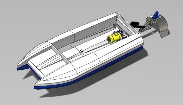
Our drivetrain this year was rather complex as we made a combination surface drive and Levi drive which allowed the propeller angle to be changed vertically. We also used a rudder shroud rotated horizontally to vector our thrust for steering.
A universal joint coupled just behind the boat allowed for the proper vertical range of motion of the drive shaft even at over 3000 RPM. This joint was covered by a rubber bellows and coated in marine grease, with double-sealed metal mounting plates forming a water-tight connection to the shaft from the motor-driven belt drive. This system works very well for maneuverability but it isn't particularly hydrodynamic— however, this can be addressed easily with some lightweight 3D-printed conic sections.
However, budget constraints prevented us from getting a proper propeller (or two), so we ended up with poor mechanical efficiency at the competition. We also believe that due to the incredible power our motor can produce, it might be better to run it at lower speeds with a higher gear ratio, as it should still produce plenty of torque while running far more efficiently. More on that later.
Drive System Electronics
The drive system electronics encompass all systems operating off the high voltage (typically 36 volt) battery set, including any motor that is used for turning propellers, and the controllers for those motors.
These must be carefully chosen: They determine to a huge extent the performance of the boat and its mechanical requirements (what diameter shaft for the propeller, the RPM levels needed for bearings and joints on said shaft, the ideal propellor RPM/pitch, etc). Many hours could be spent just on this topic. It requires a good deal of research in its own right.
Several teams at this year’s competition had one or two motors. Our boat was the only one to use a three-phase AC motor, which we got a great deal on paired with a Curtis controller which runs off DC battery power. It is fairly large and heavy, and extremely powerful, but also very reliable and electrically efficient relative to many DC motors.
We obviously power a single propellor with this motor, though in the past teams have used single motors for multiple props. This year, at least a couple of teams were using two motors for one prop. The high-efficiency standards demanded by the competition makes brushed (permanent magnet) DC motors a poor choice, but they are also very inexpensive relative to their better brushless counterparts. However, where efficiency and power are paramount, AC motors reign. (Tesla uses them, after all).
Click to enlarge.
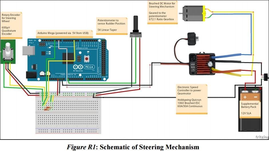
We also have our surface drive mechanism and drive-by-wire system, which utilize 12-volt power for a gear-motor and linear actuator. The steering motor is a Banebots RS 540 motor utilizing a custom 672:1 planetary gearbox for maximum torque, bringing its no-load rpm of over 16000 to less than 10 rpm, with enough torque to loosen lug nuts on a car tire. The actuator is an off-the-shelf model from ServoCity, a “super duty” actuator capable of moving 500 pounds no problem. I designed the drive-by-wire electrical system, myself, to be cheap but very capable, with an easily replaceable motor and controller.
The motor/controller combo together cost under $30, but the planetary gearbox was pretty expensive— but it also has almost no risk of failure.
The combination of a sensing potentiometer and a slow-speed, high-torque motor meant a custom-made PID control loop can be used to drive the rudder almost like a typical hobby servo. It's capable of this with absolute position, despite there being no way to sense exactly what the motor shaft itself was doing.
The quadrature encoder is instead mounted to the steering wheel and provides the Arduino with the desired target angle for the PID control loop. It would have been too easy to break a typical potentiometer if it were attached to the wheel, and using an encoder allowed for on-the-fly sensitivity changes. The only potential issue was the controller being designed for an RC car, since it only allowed for 30A continuous in reverse as opposed to 60A continuous forward.
Fortunately, our motor stall torque is only just above 30 amps, so it never continuously draws more than 5A and runs full speed in both directions.
Solar System
We were lucky and got our hands on very powerful and efficient solar panels, but all that power goes to waste without a good solar charger. We ended up getting a very efficient solar charger using MPPT to replace the bulky old house solar charger we had used previously. At a fraction of the weight, it was certainly a good investment.
Unfortunately, our charger can't quite keep up with the full power output of our panels, which can be over 10A. Solar charging from a consumer standpoint is actually very simple. All you need is panels that supply the power you need, a solar charger that works at the correct voltage for those panels, and batteries that work at the right voltage for the charger.
However, since we needed a 36-volt battery system, we were restricted to controllers like this one designed for golf carts, as home solar is usually 12V or 24V:

The solar golf cart boost charge controller we used. Image courtesy of Genasun.
However, this was beneficial, as the charger is designed for outdoor use and came waterproof.
Auxiliary Systems
It’s always great to have some extra systems in place for monitoring the speed, motor RPM, and other performance aspects of these boats. For our boat, we decided to go all out and construct an entire console, complete with LCD display powered by a Raspberry Pi, GPS gyroscopes, accelerometers, voltage monitors, and a nice readout of any other helpful data. All manual controls were also added to the console. We’re definitely going to improve on it more next year.
.jpg)
End Result
Here are the results of our hard work:


As a bonus, here's our team video and a slideshow of our build process. Enjoy!