 Facebook
 Google
 GitHub
 Linkedin
Voyager Mission Anniversary Celebration Series: Introduction
In the Summer of 2017, the Voyager spacecraft will celebrate 40 years in space. All About Circuits looks at the engineering accomplishments that made this trip possible.
As the Voyager spacecraft approach their 40th year in space, AllAboutCircuits will celebrate the accomplishments with a weekly series of articles that reminds readers of the electrical engineering accomplishments of a past generation.
For each of the next nine weekends, AAC writers will focus on different aspects of the Voyager mission design. We hope that our readers who were involved in the program take the opportunity to provide first-hand commentary on their experiences in the forums or discussion area below.
Check out the rest of the series here:
- The RTG (Radioisotope Thermoelectric Generator)
- Long Distance Communications
- Command, Data, and Attitude Control Computers
- Cameras, Polarimeters, and Magnetometers
- Infrared Interferometer, Spectrometer, and Radio Astronomy
History of Voyager 1 and 2
Video above can also be seen on NASA's Jet Propulsion Laboratory site
The Grand Tour
The two identical Voyager space probes were launched in the summer of 1977 on a trajectory that would take the spacecraft to the outer planets and moons of the solar system. At each encounter, the spacecraft gained speed for a final trajectory that would lead them out of the solar system and into interstellar space.

Graphic shows path of Voyager I and Voyager II over the last 40 years. Voyager 1 moves above the ecliptic plane and Voyager 2 moves below the ecliptic plane. Credit: Mark Hughes (based on work from Thomas Franc)
Voyager 2 launched first on August 20, 1977, on a slow path that visited the planets and moons of Jupiter, Saturn, Uranus, and Neptune. Powered by three radioisotope thermoelectric generators (RTGs) and armed with an array of science experiments, it took advantage of a unique arrangement of the solar system to visit the outermost planets in a single, uninterrupted journey.
Voyager 2 is the slower of the two spacecraft and is currently traveling through the heliopause as it journeys towards interstellar space. It's also the only of the two spacecraft to visit all four outer planets (and their moons). While on its grand tour, it delivered ~18,000 photographs near Jupiter, ~16,000 photographs near Saturn, ~8,000 photographs near Uranus, and ~10,000 photographs near Neptune.

Voyager 2 timeline shows historic and select critical engineering moments, with available power output declining over time
Voyager 1 launched 16 days after Voyager 2 on September 5, 1977, on a faster trajectory that allowed it to overtake Voyager 2 on March 5, 1979. Its journey led it to Jupiter and Saturn where it took photographs comparable in number to those taken by Voyager 2. When it left Saturn's moons, it turned upwards, on a path out of the solar system. Voyager 1 is believed to have entered interstellar space on August 25, 2012.

Voyager 1 Timeline shows historic and select critical engineering moments, with available power output declining over time
The arrangement of the planets around the sun allowed the spacecraft to travel from planet to planet using a gravitational slingshot technique to increase their speed and change their trajectory. The interaction transfers momentum from the planet to the spacecraft.
$$-\triangle P_{\text{planet}}=+\triangle P_{\text{Voyager}}$$
$$-\text{m}_{\text{planet}}\cdot (-\triangle \text{v}_{\text{planet}})=\text{m}_{\text{Voyager}} \cdot (+ \triangle \text{v}_{\text{Voyager}})$$
Since the mass of a moon or planet used for a gravitational slingshot is significantly greater (20-25 orders-of-magnitude), the change in speed of the moon or planet used for the maneuver is insignificant.
$$\text{m}_{\text{Planet}}\cdot (-\triangle \text{v}_{\text{planet}})=\text{m}_{\text{Voyager}} \cdot (+ \triangle \text{v}_{\text{Voyager}})$$
$$-\triangle \text{v}_{\text{Planet}}=\frac{\text{m}_{\text{Voyager}}}{\text{m}_{\text{Planet}}} \cdot \triangle \text{v}_{\text{Voyager}}=\frac{10^{3} \text{kg}}{10^{27} \text{kg}}\cdot \triangle \text{v}_{\text{Voyager}}\approx 0$$
The insignificant effect to the larger body is similar to what would happen to a tennis ball that bounced off of the front of a fast-moving train—the tennis ball would leave with a new direction of travel and a new speed, while the train would slow down only imperceptibly.
A spacecraft that enters the region of space near a planet or a moon will experience a force in the direction of the center of mass of the planet. When approaching a moving planet, the impulse (change in momentum) that the spacecraft experiences as it moves towards the planet is different from the impulse that the spacecraft experiences as it moves away, and the result is an accelerated spacecraft.

As a spacecraft approaches a planet, it can fly into a region of space behind the planet's direction of travel to gain speed, or it can fly into a region of space in front of the planet's travel to reduce speed.
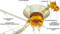
About the Spacecraft

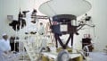
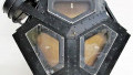
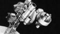
The Voyager 1 and Voyager 2 spacecraft have identical design and instrumentation.
In this series of articles, released in these weeks leading up to the 40th anniversary of the launch of the Voyager Spacecraft, AAC will examine and explain several aspects of that mission, including:
- Power: Three plutonium-238 powered radioisotope thermoelectric generators power each spacecraft.
- Communications: Very long distance microwave communication transmit control data to the spacecraft and from the experiments back to Earth for analysis.
- Computers and data processing: Voyagers' computers were engineered without microcontrollers, and data was stored on magnetic tape.
- Scientific instruments
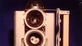
- Cameras: One wide-field 200 mm focal length camera and one narrow-field 1500 mm focal length camera and an array of filters provide photographs and a means of analyzing planets and moons
- Radio science systems: Analyze the disturbance of radio signals from the communications system to infer mass, density, and shape of the interfering object
- Infrared interferometer, spectrometer, and UV spectrometer: Broad-spectrum, high-resolution, low-noise instruments enable the analysis of the atmosphere of planets and moons
- Triaxial fluxgate magnetometer: Two low-field (2 pT to 50 µT) and two high-field (12 nT to 2 mT) magnetometers allow for the inspection of magnetic fields near planets and moons as well as in interplanetary and interstellar space
- Plasma spectrometer: Two Faraday cup plasma detectors analyze the velocity, density, and pressure of plasma ions at the interstellar and planetary level
- Low-energy charged particle instruments: Multiple electron detectors (15 keV to 1 MeV) and ion detectors (15 keV/nucleon to 160 MeV/nucleon) (These are used to gather information about charged particles (electrons, protons, ions) in interplanetary space and in a planet's magnetosphere.)
- Cosmic ray detectors: Multiple particle detectors (0.5–9 MeV, 4–500 MeV, 7–100 MeV) determine the composition of and measures the energy spectrum of cosmic rays
- Planetary radio astronomy: A 20 kHz to 40.5 MHz radio receiver studies the radio emission of Jupiter, Saturn, and their satellites
- Photopolarimeter: Polarizing filters are used to investigate the physical properties of a planet's atmosphere
- Plasma wave system: Measures thermal plasma density and electric field components while the spacecraft is in the magnetosphere of Jupiter or Saturn
Conclusion
The Voyager mission is a culmination of incredible feats of engineering, all of which involve electrical systems or circuits. New articles will be presented weekly, and we hope that you check back each Sunday for new material and join in discussions in the forums or in the comments section below.


This is an excellent idea