 Facebook
 Google
 GitHub
 Linkedin
The Brains of the Voyager Spacecraft: Command, Data, and Attitude Control Computers
Learn about the computers at the heart of the Voyager spacecraft operations.
How do the Voyager spacecraft orient themselves in space and coordinate their systems? Learn about the brains of the spacecraft: the command, data, and attitude control computer systems.
This is the fourth installment of the Voyager Mission 40th Anniversary Celebration series. Catch up on the other articles in this series below:
- Introduction
- RTG (Radioisotope Thermoelectric Generator)
- Long Distance Communications
- Cameras, Polarimeters, and Magnetometers
- Infrared Interferometer, Spectrometer, and Radio Astronomy
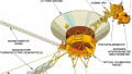
Launched in 1977, the Voyager 1 and 2 probes were both cutting-edge pieces of technology for their time. The computers at the heart of their operations consisted of three systems, each with dual-redundancy, that worked together to enable the probes to journey to Jupiter, Saturn, and beyond: the Computer Command System (CCS), the Flight Data Subsystem (FDS), and the Attitude and Articulation Control System (AACS).
What is amazing is that even after four decades of traveling through the harsh, sometimes unpredictable, environment of space, both probes continue to function and call home with new insights and data. It is taking longer and longer to be able to communicate and upload new routines to the probes, but the fact it is still possible with technology from a bygone era is a testament to the quality of engineering put into these spacecraft.
The story of how the Voyager computers took shape is a fascinating one. Coming together during NASA budget cuts after the excitement of the Apollo era faded, and overcoming challenges not yet encountered by engineers in exploring some of the most interesting places in our solar system, the details will surely give one a greater appreciation of the Voyager computers.
Development and Management
The process of development and management of computer hardware and software might not be the most exciting part of the process, but it is one that is incredibly crucial to the final outcome.
One of the first design decisions made about the Voyager computers was the use of the Viking Computer Command System (CCS). This not only satisfied a proposal to standardize the computer system but was also a decision fuelled by NASA budget cuts after the Apollo missions in the 1970s. Unmanned space exploration became much less of a priority during this time, and so keeping cost developments low was important to allow the overall project to continue.

Viking CCS memory. Image courtesy of NASA.
The new elements to the overall Voyager computers would be the Flight Data System (FDS) and the Attitude Articulation Control System (AACS). The CCS would be responsible for commands and memory management of the FDS and AACS, which required the addition of a MEMLOAD routine (to load memory, as implied) and an AACSIN routine for health monitoring of the AACS.
Each computer system on the Voyager spacecraft was dual-redundant— there were two CCS’, two FDS’, and two AACS’. The CCS typically remained on at all times, but the FDS would usually only operate one at a time, and the AACS would only ever operate one at a time. The idea was that regular dormancy of computer systems not actively in use would help maintain the lifespan of the systems.
The Voyager CCS and Viking CCS would ultimately have the same amount of memory (just under 70kB) despite the routines and programs for Voyager being much more complex. In-flight programming allowed for new routines and programs to be uploaded regularly in non-volatile memory and eliminated the need for large amounts of memory to be required onboard.
The original software for the Voyager probes was written using Fortran 5 then ported to Fortran 77, and today there is some porting in C. Low-level, light-weight software is increasingly important as the probes move farther and farther away from Earth and communication becomes slower.
The management side of the Voyager computer system also saw some changes to the typical structure; H. Kent Frewing, a spacecraft software engineer, would manage the engineers responsible for each computer system and up to four programmers would work together on the project at once. An On-Board Software Design Team was put together to guide software development, and software validation was completed by the Capability Demonstration Laboratory. Once the initial software had been developed, hardware that was set up in the same configuration that would be used onboard the spacecraft would then be used to test and continue development.
Computer Command System
As mentioned previously, the Voyager CCS would be nearly identical to the Viking CCS, with some modifications to allow interfacing with the FDS and AACS. The Viking CCS was the first redundant computer system implemented by JPL (NASA's Jet Propulsion Laboratory), with a relatively simple design that enabled much greater computing power.
The Viking CCS had two of everything: power supplies, processors, buffers, inputs, and outputs. Each element of the CCS was cross strapped which allowed for “single fault tolerance” redundancy so that if one part of one CCS failed, it could make use of the remaining operational one in the other.
The CCS could also operate in three modes: individual (each CCS completes tasks independent of one another), parallel (both CCS work on a task together), or tandem (each CCS works on the same task independently). During near encounters with targets (Jupiter, Saturn, etc.), the CCS would be in tandem mode.
Block diagram for Viking and Voyager CCS. Image courtesy of NASA.
The CCS is responsible for managing overall operations, including program sequencing, monitoring the health of the probes, communicating with the other computers, and uploading programs to memory.
Both CCS modules in the dual-redundant system would be on continuously. This allowed for increased processing capability and would become increasingly important upon encounters with Jupiter, Saturn, Uranus, and Neptune to collect data.
On an architectural level, the CCS processors contained an instruction interpreter, data path control, and registers (18-bit accumulator, 12-bit link register, 12-bit program counter, 4-bit condition code register) which operated in serial. Instructions were 18-bit words, with the most significant 12-bits containing addresses (4k of direct addressing), and the least significant 6-bits containing operation codes (64 instructions).
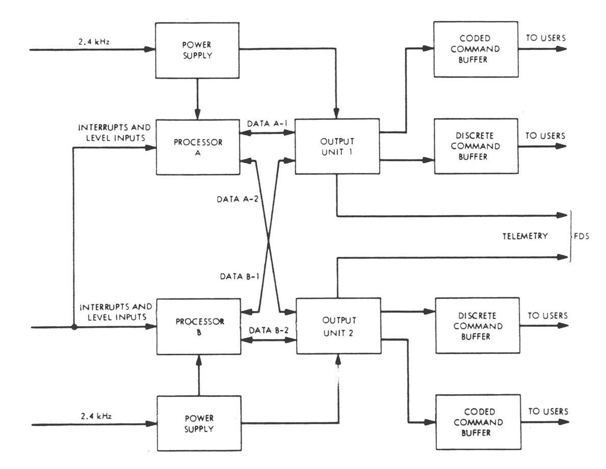
Flight Data System
The FDS is where engineering and science data was collected, formatted, and stored on the Voyager probes, and where all telemetry was collected. The development of the FDS began with a graduate paper which described the overall requirements of the FDS, as well as the trade-offs and benefits of hardware or software implementation, including which functions work best in each.
One of the most important considerations for the FDS was the input/output data rates. As sensors and data-collecting hardware became more sophisticated, the resolution of the information it needed to transmit increased. In the Voyager probes, if possible, data would be transmitted at a high rate back to Earth. However, if this rate could not be achieved (if it was not able to communicate with the tracking station, for example), then the data was stored on magnetic tapes. These magnetic tapes are still being used repeatedly for data collection and transmission onboard the probes today as they sail through interstellar space.
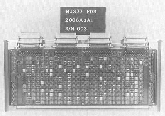
Voyager FDS. Image courtesy of NASA.
The Voyager FDS would be the first spaceflight computer to use CMOS volatile memory. This was a big step since it was a fairly new technology and, if power was lost to the ICs for a moment, all memory would be lost, too. However, a direct line from the radioisotope generators, which provided direct current, was used to ensure the CMOS ICs would never lose power unless something happened to the generators. It was decided that, if something had happened to the generators that rendered them inoperable, there would unlikely be a need for the FDS, anyway.
The CCS and FDS were designed separately because of the input/output rates required by the FDS, even if computationally they could have easily been integrated together. The Voyager probes would be the last probes built by JPL to keep these functions separate, however. The FDS, like the CCS, is programmable in-flight, allowing for optimization or changes.
Attitude and Articulation Control System
The AACS of the Voyager probes determine the orientation, keeping it pointed towards Earth. The original intent of the designers was to use a new technology called “HYSPACE” (Hybrid Programmable Attitude Control Electronics) for the AACS. HYSPACE combined analog and digital elements, used index register addressing, and 4-byte serial architecture. This permitted the use of the same code for all three axes of the AACS.
However, pressure was put on the team to re-use the Viking CCS for the attitude control as well, since it was capable and would cut costs on the development of a new system from scratch.
In the end, a modified version of the CCS was used, with some elements of HYSPACE incorporated to gain the benefits of index register addressing. In documentation, the AACS is still referred to as HYSPACE even though it’s a modification of it.
The AACS has four routines that could be executed: scan platform stepper motors, thruster actuators, attitude control laws, and thruster logic. The AACS also sent a “heartbeat” to the CCS at regular intervals.
Conclusion
The unique climate at the time of the Voyager probes’ development greatly shaped the overall outcome of the computer systems that were used. Reusing designs and modifying them to cut down on costs, optimizing the use of limited memory, and maximizing speed without increasing the need for power are still problems modern space projects face today.
Still, it is incredibly impressive that not only did the team behind the Voyager computers pull off low-cost, efficient, and computationally powerful designs, but that all their forward thinking and clever engineering has enabled both probes to continue to operate, with expectations they will do so for at least another decade.
Sources
- https://history.nasa.gov/computers/Ch6-2.html
- https://history.nasa.gov/computers/Ch5-6.html
- https://www.wired.com/2013/09/vintage-voyager-probes/
- http://users.cecs.anu.edu.au/~Jonghyuk.Kim/teaching/KF%20Voyager.pdf
Featured image courtesy of NASA
Related Content


What are the operating voltages of the TTL and CMOS logic in the CCS, FDS, and AACS?
Great article! The 2013 WIRED article used as source had some unfortunate mistakes, so there are a couple of mistakes in this article.
*** “The Voyager CCS and Viking CCS would ultimately have the same amount of memory (just under 70kB) ...”
The total amount of memory for all 6 computers on a spacecraft was the equivalent of around 70kB. Each of the two CCS and two AACS computers has 4,096 18-bit memory words (equivalent to 9KB), requiring 12-bit addresses as you correctly note further down in the article. Each of the two FDS computers has 8,192 16-bit memory words (equivalent to 16KB). If you add up the total bits and divide by 8, you get the 70kB figure.
*** “The original software for the Voyager probes was written using Fortran 5 then ported to Fortran 77, and today there is some porting in C.”
These were misunderstood remarks by the author of the WIRED article. The ground-system software running on Univac mainframe computers was written in Univac Fortran V (“Fortran five”); it was later ported to Fortran 77. Circa 1990, the ground system was moved off the mainframes and the software was substantially re-implemented in C and run on Unix workstations. The onboard CCS, AACS, and FDS computers are all programmed in their respective assembly languages.