Facebook
 Google
 GitHub
 Linkedin
Create Your First Application with TI’s LaunchPad
Texas Instruments' LaunchPad makes developing applications with MSP430 microcontrollers easy and fast. Learn all about it and create your first application.
In this article, we will introduce TI’s LaunchPad, which makes developing applications with MSP430 microcontrollers easy and fast.
Texas Instruments’ MSP430 family of microcontrollers occupies an important place in the electronics world: on the one hand, they have excellent ultra-low power consumption rates, and on the other hand, they provide very powerful features in terms of peripherals, memory size, speed, and ease of use.
In this article, we will introduce TI’s LaunchPad, which makes developing applications with MSP430 microcontrollers easy and fast. LaunchPad is an inexpensive MSP430 prototyping tool that provides on-board emulation for programming and debugging. There are many advanced versions of LaunchPad featuring different peripherals, but we will use the base version called the “original LaunchPad.”
LaunchPad Hardware
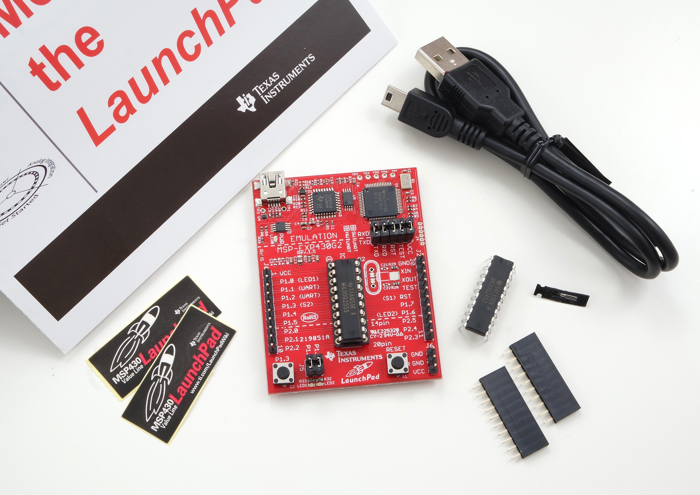
LaunchPad comes in a kit which includes the following:
- 1 x LaunchPad Development Board
- 1 x M430G2553IN20 Microcontroller
- 1 x M430G2452IN20 Microcontroller
- 1 x 32.768 KHz Crystal
- 2 x 2.54 mm 1x10 Female Header
- 1 x USB-A to Mini-USB Cable
- 2 x LaunchPad Stickers
On the LaunchPad, there is an emulation section for USB programming and debugging, one general purpose button, two general purpose LEDs, one reset button, two port expansion headers, and a 20-pin target socket.
The board gets its power from the mini USB port at 5V level and converts it to 3.6V with the help of the on-board LDO regulator. The emulation section and the microcontroller needs a voltage at this level to operate. 3.6V net is labelled as VCC on the board and VCC and GND lines are expanded to J1, J2 and J6 headers.

The emulation section builds an interface between the microcontroller and the programming environment. It lets the user program the device memory and debug the embedded code step by step to inspect the program execution and the internal registers. Emulation sections also include an USB to UART converter which can be configured to interface the microcontroller with a PC over serial communication.
The green and red LEDs on the board are very useful peripherals that provide visual indication of feedback during the program execution. The general purpose pushbutton can be used to trigger an event when it is pressed. The reset button restarts the microcontroller and returns it to its initial state.
LaunchPad comes with two 16-Bit microcontrollers: MSP430G2452 and MSP430G2553. They are both 20 pin devices. General properties of these microcontrollers are listed below and the differences between them are highlighted.

Both microcontrollers have built-in programmable 16MHz clock sources. In addition, LaunchPad allows the user to connect an external clock source such as a 32.768kHz watch crystal or any other standard crystal up to 16MHz. An SMD footprint and a through-hole footprint are provided to let the user use crystals in different packages. If extra crystal capacitors are needed, the board also includes reserved footprints C21 and C22 for this purpose.
Another great feature of the microcontrollers is the built-in temperature sensor. It is a linear sensor which outputs 3.55mV/C. The sensor output is internally connected to one of the ADC inputs and the user should select that input to be able to read the temperature data from the sensor.
All the pins of the microcontroller are expanded to the J1 and J2 header to easily use the device ports while prototyping. J1 and J2 footprints come unassembled so you can connect a male or a female header depending on your needs.
Programming Tools
There are various integrated development environment (IDE) options available for LaunchPad for coding, device programming and debugging purposes.
Energia
Energia is an open source community-driven code editing tool developed for LaunchPad. It is supported on Mac OS, Windows, and Linux. Energia uses the Wiring and Arduino framework so its user interface is nearly the same as Arduino IDE. Energia is totally free and supports all the LaunchPad boards.

Code Composer Studio (CCS)
Code Composer Studio (CCS) is a professional development tool made by TI which also supports all the LaunchPad boards. It can be downloaded and installed on a PC or the cloud version can be used on a web browser. CCS comes with 16KB code size limitation in free usage. Since the MSP430 on the Launchpad Original is a 16KB device, this is not a problem.
CCS Cloud allows you to develop, compile, flash and debug your code all in a web browser. In the cloud environment, there are also other useful features such as exploring and importing examples from the MSP430 resource center, make GitHub integration, communicate your Launchpad via serial monitor, etc.

The downloadable and full-featured version of CCS is also available. It is Eclipse based and supports all the TI processor devices, including LaunchPad. Registration on TI website is required before download.

Third Party IDEs
There are many other third part development tools for LaunchPad. Keil and IAR Embedded Workbench are complete debugger and compiler toolchains. GCC is an open-source compiler supporting TI’s LaunchPad. Temboo is an online development platform which also supports LaunchPad.
A Simple Application with LaunchPad
After a brief introduction to the LaunchPad hardware and the development tools, we can build our first application by using the on-board peripherals and the Energia IDE. We will use the LEDs and the pushbuttons to demonstrate how to set port directions, read an input and set an output.
Launch Energia and create a new sketch by using File > New. A new sketch file including an empty setup() and an empty loop() functions will appear. In the setup function, we should set the port directions by using the pinMode() function. The GREEN_LED and the RED_LED pins should be outputs and the pushbutton pin PUSH2 should be an input. Not to use an external pull-up resistor, the internal pull-up of PUSH2 pin should be enabled by usingh the INPUT_PULLUP option.
void setup() {

  // initialize the on-board RED and GREEN LED pins as output:
  pinMode(GREEN_LED, OUTPUT);
  pinMode(RED_LED, OUTPUT);

  // initialize the on-board PUSHBUTTON pin as an input:
  pinMode(PUSH2, INPUT_PULLUP);
}
In the main loop will read the pushbutton input by using the digitalRead() function. We check the button status by using the “if” statement. When the button is not pressed, digitalRead() function returns 1 since the PUSH2 pin is internally pulled high. In this state GREEN_LED blinks. Blinking is implemented by turning the led on and off periodically by using the digitalWrite() function in 100ms intervals. delay() function helps us at this point to create a desired waiting time interval. When the button is pressed, the button pulls the PUSH2 pin to GND and digitalRead() function returns 0. This time GREEN_LED is turned off and RED_LED starts to blink.
void loop(){

  // check if the pushbutton is pressed.
  if (digitalRead(PUSH2)) {
   // blink the GREEN LED:
   digitalWrite(RED_LED, LOW);
   digitalWrite(GREEN_LED, HIGH);
   delay(100);
   digitalWrite(GREEN_LED, LOW);
   delay(100);
  }

  else {
    // blink the RED LED:
   digitalWrite(GREEN_LED, LOW);
   digitalWrite(RED_LED, HIGH);
   delay(100);
   digitalWrite(RED_LED, LOW);
   delay(100);
  }
}
The complete sketch is given below.

When the sketch is ready, just click the Verify button to compile the code. If there is no error, Energia will display "Done compiling" message. Otherwise the errors will be listed in the message tab. After the compilation finishes successfully, you can flash your device by clicking the Upload button. Make sure that you already selected the right serial port of your LaunchPad by using Tools > Serial Port menu and the LaunchPad model you are using (For Example LaunchPad w/ MSP430G2353 (16MHZ)) by using Tools> Board menu. You can see the code in action on the video below.
Give this project a try for yourself! Get the BOM.