 Facebook
 Google
 GitHub
 Linkedin
Create Your Own Stylus-Controlled Synthesizer
In this project article, we'll use a 555 timer IC to build an iconic musical instrument from the early days of synthesizers.
In today’s project, we’ll design and build our own version of the Stylophone, a miniature, stylus-operated synthesizer whose sound features prominently in David Bowie’s “Space Oddity” and Kraftwerk’s “Pocket Calculator.” In Bowie’s honor, we’ll call it the Ziggy Stylus.
The original Stylophone’s keyboard took the form of 20 metal pads printed directly onto a PCB. Closing the circuit between any one of these pads and the stylus triggered an oscillator-controlled speaker to buzz at a specific frequency, creating a distinct electronic tone. Our version, which is pictured in Figure 1, will be built around a 555 timer IC and feature a 25-note keyboard.
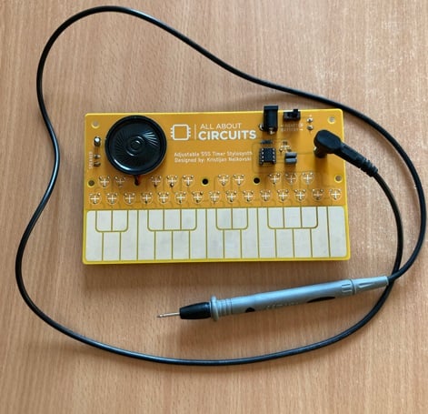
Figure 1. The fully assembled Ziggy Stylus. Image used courtesy of Kristijan Nelkovski
Project Requirements and BoM
As you can see in the figure above, I used a multimeter probe for the stylus. You could also use a jumper wire or an alligator clip wire. Really, any type of wire-and-conductive-tip combination will do.
The bill of materials (BoM) for this project is shown in Table 1.
Table 1. BoM for the Ziggy Stylus synthesizer.
| Part | Quantity | Designation | Notes |
| 555 timer | 1 | - | The main IC for this project. |
| 10 nF capacitor | 1 | C2 | - |
| 0.1 μF capacitor | 1 | C1 | - |
| 4.7 μF capacitor (electrolytic) | 1 | C3 | - |
| Speaker (with wires) | 1 | - | Any speaker will do. |
| 25 kΩ potentiometer | 1 | R27 | - |
| 4.7 kΩ potentiometer | 25 | R1 through R25 | For individual notes/keys. |
| 2 kΩ resistor | 1 | R26 | - |
| Speaker connector | 1 | SPK TERMINAL | - |
| Power connector | 1 | PWR JACK | - |
| Barrel jack | 1 | PWR TERMINAL | - |
| Switch | 1 | SWITCH | For switching between barrel jack and power connector/battery. |
| Power source | 1 | - | To power the Ziggy Stylus. |
| Stylus | 1 | MOUNT-PAD-ROUND4.5 / STYLUS | I used a multimeter probe with a 4.5 mm connector. Your mileage may vary. |
| Custom PCB | 1 | - | Easy-to-make, single-sided design. |
Unlike most of my other projects, this one is not breadboard or perfboard friendly. To make it, you’ll need to produce your own PCB. Fortunately, the design is quite simple, so you can get away with a basic, single-sided, DIY PCB. I've included the Eagle CAD files below:
Ground Control to C-Major Tom: Music Theory and Electronics
Because we’re designing a musical instrument, we need to cover some basic music theory before we proceed. We’ll start with the simplest unit of music: the note.
A musical note is a sound characterized by its pitch and duration. The pitch of a note is associated with the frequency of its physical oscillations expressed in hertz. If we consider musical notes in terms of oscillations, it stands to reason that we can electronically recreate them by generating a signal of the same frequency. This electrical signal can then drive a transducer, such as a speaker or a buzzer, to produce an audible sound wave.
Understanding Musical Notation
Western musical notation uses a 12-note scale. Each note on the scale represents an increase in pitch from the one before it. After the 12th note, the scale repeats, but the frequency of each note is double what it was before. The distance from one note to its nearest counterpart—the note with either one half or two times its frequency—is called an octave.
The scale can be divided into:
- 7 natural notes.
- 5 accidental notes.
The natural notes are named after the first seven letters of the Latin alphabet (A, B, C, D, E, F, G). However, it’s more common to begin the sequence with C. The sequence then goes C, D, E, F, G, A, B.
Accidental notes are defined by their relationship to natural notes. Each accidental note is a half-step higher than one natural note and a half-step lower than a second one. We refer to the accidental note either as the sharp(♯) of the former note or the flat (♭) of the latter. For example, the note between C and D could be called either C♯ or D♭. In this project, I’ve chosen to use sharps rather than flats.
The Keyboard Layout
Figure 2 shows the 12-note scale as it appears on a piano keyboard. As you can see, the white keys correspond to natural notes. The black keys on a piano play accidental notes.
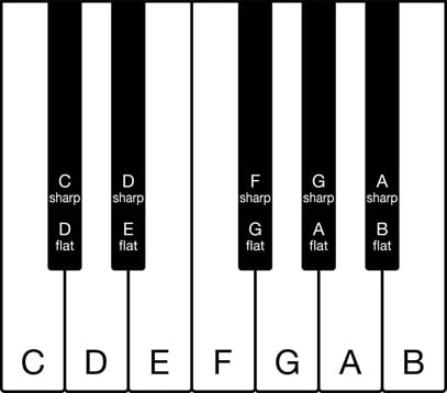
Figure 2. One full octave on a piano. Image used courtesy of Adobe Stock
The Ziggy Stylus features the 25 notes from C3 to C5, which is to say:
- All 12 notes of the third octave on the scale.
- All 12 notes of the fourth octave.
- The first note of the fifth octave.
Figure 3 shows the locations of these notes on the synthesizer keyboard. The original image was created in the Altium 365 viewer using the Eagle CAD files included in the previous section.
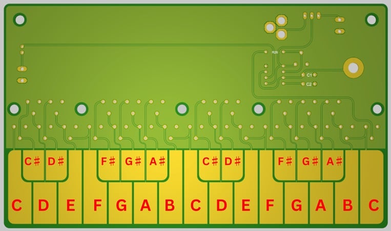
Figure 3. The keyboard of the Ziggy Stylus is organized like a piano’s. Image used courtesy of Kristijan Nelkovski
With that, we’re ready to stop discussing theory and start looking at the actual circuitry. If you want to know more about the concepts and terms in this section, however, the Musicca website is a good resource.
Circuit Design for the Ziggy Stylus
To generate the necessary electronic signals, we’ll use a 555 timer IC (Figure 4) as an astable oscillator. Designed by Hans Camenzind in 1970, the 555 timer is one of the most popular integrated circuits ever made.
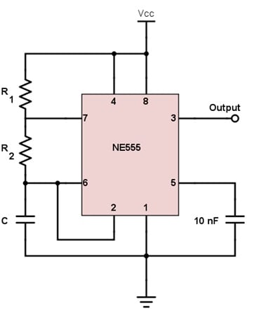
Figure 4. A 555 timer IC configured as an astable circuit. Image used courtesy of All About Circuits
I used All About Circuits’ 555 Timer Astable Oscillator Circuit tool to calculate the values for each one of our components. However, this tool has fields for three inputs: C, R1, and R2. Compare this to Figure 5, which shows the schematic for the Ziggy Stylus.
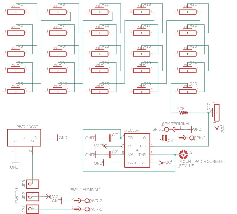
Figure 5. [Click to enlarge] The Ziggy Stylus circuit schematic. Image used courtesy of Kristijan Nelkovski
As you can see, there’s a lot more than just R1 and R2 here. In fact, R1 corresponds to R27 in this circuit. R2 is replaced by a chain of 25 potentiometers wired in series, each with one lead connected to an individual copper pour pad. This way, the total resistance between R1 (the first of these potentiometers) and any single pad will equal the sum of all potentiometers in the chain up until that point.
Normally, the circuit will be open at the node between the 25-resistor series and pins 2 and 6 of the 555. Hooking up these two pins to a stylus allows us to dynamically close the circuit by touching the stylus to one of the copper pour pads. Each pad will act as an individual music key when the project is complete.
Frequency Tuning
Next, we adjust the potentiometer resistances to produce the desired frequencies. For the range of notes in Figure 3, we set the 25 kΩ potentiometer (R27) to 22.5 kΩ and set the 4.7 kΩ potentiometers (R1 through R25) to the values given by Table 2. The table also includes the notes the frequencies will ultimately produce.
Table 2. Resistance settings for potentiometers R1 through R25, along with the frequencies and pitches they produce. Frequency and pitch data used courtesy of muted.io
| Potentiometer | Resistance Setting (kΩ) | Frequency (Hz) | Note | Octave |
| R1 | 3.2 | 130.81 | C | 3 |
| R2 | 2.6 | 138.59 | C♯ | 3 |
| R3 | 3.0 | 146.83 | D | 3 |
| R4 | 2.5 | 155.56 | D♯ | 3 |
| R5 | 2.5 | 164.81 | E | 3 |
| R6 | 2.3 | 174.61 | F | 3 |
| R7 | 2.3 | 185.00 | F♯ | 3 |
| R8 | 1.9 | 196.00 | G | 3 |
| R9 | 2.0 | 207.65 | G♯ | 3 |
| R10 | 1.9 | 220.00 | A | 3 |
| R11 | 1.6 | 233.08 | A♯ | 3 |
| R12 | 1.7 | 246.94 | B | 3 |
| R13 | 1.6 | 261.63 | C | 4 |
| R14 | 1.4 | 277.18 | C♯ | 4 |
| R15 | 1.4 | 293.66 | D | 4 |
| R16 | 1.3 | 311.13 | D♯ | 4 |
| R17 | 1.25 | 329.63 | E | 4 |
| R18 | 1.15 | 349.23 | F | 4 |
| R19 | 1.1 | 369.99 | F♯ | 4 |
| R20 | 1.0 | 392.00 | G | 4 |
| R21 | 1.0 | 415.30 | G♯ | 4 |
| R22 | 0.9 | 440.00 | A | 4 |
| R23 | 0.9 | 466.16 | A♯ | 4 |
| R24 | 0.7 | 493.88 | B | 4 |
| R25 | 0.5 | 523.25 | C | 5 |
Playing Music on the Ziggy Stylus
Now that we have something resembling a musical instrument, all that’s left is to connect the 555’s output to a speaker. Every time the stylus touches one of the synthesizer’s keys, the 555 will drive the speaker to produce notes at the predetermined frequencies. As I stated in the BoM, any speaker will do.
Once we’ve done that, the Ziggy Stylus is ready to play! Click on the video in Figure 6 to hear me try it out.
Figure 6. Testing the Ziggy Stylus. Video used courtesy of Kristijan Nelkovski
Your Turn
Now that we’ve confirmed the Ziggy Stylus works, it’s up to you to build your own. You can scale it up or down, connect it to other circuits, play around with different components, or adjust the potentiometer values to get different output frequencies. These frequencies don’t necessarily have to correspond to conventional musical octaves. If you have an idea for making this project your own, feel free to let us know in the comments!
Featured image used courtesy of Kristijan Nelkovski; background graphics used courtesy of Canva
Related Content


555 timer everywhere 😅
I’ve never worked with metal pads on a pcb before. Could you explain where I should get them and how to install them on the circuit board?