 Facebook
 Google
 GitHub
 Linkedin
Design a Color Sensor with Measurements Displayed via an RGB LED Module, Part 2
Learn how to collect and process RGB data generated by the BH1745NUC color sensor IC.
Collect and process RGB data generated by the BH1745NUC color sensor IC.
Supporting Information
- Custom PCB Design with an EFM8 Microcontroller
- Introduction to the I2C Bus
- The I2C Bus: Hardware Implementation Details
- The I2C Bus: Firmware Implementation Details
- Implementing I2C with an EFM8 Microcontroller, Part 1
- Implementing I2C with an EFM8 Microcontroller, Part 2
Previous Article in This Series
The Sensor
In Part 1 we discussed how to use a DAC and some negative feedback to precisely control the intensity of red, green, and blue LEDs. We can now use our RGB LED module as a single-pixel display—i.e., by manipulating the mixture of red, green, and blue light, we can produce a wide range of colors.
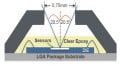
We want to use this LED module to duplicate the color of light illuminating our RGB sensor. As mentioned in the first article, we are using the BH1745NUC color sensor IC manufactured by Rohm (hereafter abbreviated as BH1745). This is actually a fairly impressive device. The package is miniscule (about 2 mm × 2 mm), which is one reason why we are using a custom-designed PCB for this project (maybe you could solder jumper wires onto eight microscopic 0.5-mm-pitch lands, but I couldn’t). And despite this small size, the part incorporates extensive functionality and requires only a few external components. Here is the “typical application circuit” from the datasheet:

Optical filters, four photodiodes, four separate 16-bit ADCs with whatever signal-conditioning circuitry is needed, an I2C interface, and some interrupt logic that can be used to alert the microcontroller whenever the red, green, blue, or clear measurement goes above or below customizable thresholds—I’d say that’s pretty good for something so tiny and inexpensive ($1.61 for a single unit at Digi-Key).
Here is the relevant portion of the schematic:

Gathering Data
The BH1745’s digital section includes a bank of 21 8-bit registers. All interaction—except the interrupt functionality, which we don’t use in this project—between the microcontroller and the BH1745 is accomplished by writing to or reading from these registers via standard I2C transactions. For an abundance of general information and practical guidance related to the I2C protocol, please refer to the articles listed under “Supporting Information.” Here we will focus on implementation details specific to the BH1745.
Controlling and retrieving data from the BH1745 requires three types of I2C transactions: write, write-before-read, and read.
- Write: These transactions are used to load data into the BH1745’s register bank. The first byte after the slave-address-plus-R/nW byte specifies the register address, then the following byte is the data to be loaded into the register.

- Write-before-read: If you are familiar with the I2C protocol, you know that a master cannot write and read data in one transaction. Every transaction is defined as a read or a write. Thus, we can’t use a single transaction to indicate a register address then read back data from that register. The solution is two separate transactions—first we write data to the BH1745 to tell it which register we want to read, then we follow up with a read transaction to retrieve data from the specified register. The first transaction in this process is what I call the write-before-read transaction.
- Read: These transactions allow the master to read data from whichever register address was transmitted in the write-before-read transaction.

As you can see, a read transaction is not limited to the one specified register address. If you continue reading bytes from the BH1745, it will automatically increment the register address and send data from the new register. Actually, you can do this same thing with write transactions:

I generally avoid the automatic-increment functionality because I value the keep-it-simple principle, which is particularly relevant here because the BH1745’s registers are not arranged contiguously (i.e., invalid register addresses are mixed in amongst valid register addresses). However, I do make use of this feature when reading RGBC data—all 8 bytes are contiguous (starting at address 0x50), and it would be seriously inefficient to frequently collect RGBC data using 16 separate single-byte transactions (8 write-before-reads and 8 reads).
Note also that the write-before-read and read transactions can be implemented with a repeated start condition (as shown in the above diagram) instead of a stop condition followed by a start condition. This would be preferable if we had multiple masters on the I2C bus (for more information, see the “Start without a Stop” section in The I2C Bus: Firmware Implementation Details). In this project, though, we have only one master, so we will again invoke the keep-it-simple principle and use a typical stop-then-start approach.
Processing Data
The RGBC data arrives from the BH1745 as four 16-bit words, as follows:

We can ignore the clear data for this project; all we need to do is convert the R, G, and B words into 8-bit values that we can use to control the intensity of the R, G, and B LEDs. The first thing to realize is that the three color detectors in the BH1745 are not equally sensitive:

From this plot we can see that R is about 0.72 and B is about 0.56 when G is 1. Thus, we need to multiply the R and B values by the appropriate correction factor:
\[CF_R=\frac{1}{0.72}=1.39,\ \ \ CF_B=\frac{1}{0.56}=1.79\]
Now we need to modify the data in a way that emphasizes the color characteristics of the incident light. Our goal here is to “measure” color, regardless of the overall intensity of the light illuminating the photodetectors. Thus, we need to scale the RGB values in a way that standardizes the absolute value of the measurements while preserving the relative value—in other words, we maximize the overall intensity while maintaining the proportion of red, green, and blue in the incident light. To accomplish this, we multiply the highest of the three measurements by whatever factor increases this highest measurement to the maximum value, then we multiply the other two measurements by the same factor. This commented code excerpt clarifies the entire process:
//extract the 16-bit R, G, and B values from the received data
R_word = (I2C_RcvData[1] << 8) | I2C_RcvData[0];
G_word = (I2C_RcvData[3] << 8) | I2C_RcvData[2];
B_word = (I2C_RcvData[5] << 8) | I2C_RcvData[4];

//apply correction factors based on the relative sensitivity of the three photodetectors
R_intensity = R_word * 1.39;
G_intensity = G_word * 1;
B_intensity = B_word * 1.79;

//determine which intensity is the highest of the three
if(R_intensity >= G_intensity && R_intensity >= B_intensity)
	MaxIntensity = R_intensity;
else if(G_intensity >= R_intensity && G_intensity >= B_intensity)
	MaxIntensity = G_intensity;
else
	MaxIntensity = B_intensity;

/*Now we scale each measurement into the range 0 to 100.
 * This preserves the relative ratios of the three
 * intensities but standardizes the absolute intensities.
 * Thus, the appearance of the LED module is
 * determined by the proportion of red, green,
 * and blue light, not by the overall intensity of
 * the incident light.*/
R_scaled = (R_intensity/MaxIntensity)*100;
G_scaled = (G_intensity/MaxIntensity)*100;
B_scaled = (B_intensity/MaxIntensity)*100;
Note that the final values are scaled such that the maximum is 100. You may recall from the previous article that the DAC has 8-bit resolution, and thus we could go as high as 255. So why am I restricting the LED intensities to 100 instead of using the full 8-bit range? Because staring at this LED module cranked up to 20 mA was messing with my vision! The light is so focused and spectrally pure that it seems to confuse the eye in an aggravating way.
Step by Step
Here is the overall procedure for configuring the BH1745, gathering data, processing the data, and updating the DAC; further details can be found in the source code.
- Write to register 0x42 to enable RGBC conversions.
- Delay 1 second (or some other appropriate interval between measurements).
- Write register address 0x50 in preparation for reading RGBC data.
- Read 8 bytes of RGBC data (for this project we need only the first 6 bytes).
- Wait until the I2C transaction is complete.
- Read the 16-bit RGB data into three unsigned 16-bit variables.
- Convert these three variables into floating point values while multiplying each one by the appropriate correction factor.
- Find the maximum of the three and scale each value as described above; store the results in unsigned 8-bit variables.
- Update the LED color by loading the 8-bit values into the appropriate DAC channels.
Firmware
Here is a link to download a zip file containing all the source and project files. You can open the “hwconf” file to access configuration details for the port pins and the peripherals. Also, note that these source files include some code that won’t be needed until later when we incorporate USB connectivity.
RGBSensorwithLEDFeedback_Part2.zip
Here are some salient code sections. First, the main() routine:
int main(void) {

	unsigned char R_scaled, G_scaled, B_scaled;
	unsigned int R_word, G_word, B_word;
	float R_intensity, G_intensity, B_intensity, MaxIntensity;

	// Call hardware initialization routine
	enter_DefaultMode_from_RESET();

	//enable global interrupts
	IE_EA = 1;

	//tell the RGBC sensor to start performing measurements
	I2C_MasterWrite(RGBC_Tx_EnableConv);

	while (1)
	{
		Delay_10ms(100);	//the LED is updated once per second

		//load the proper register address (for reading) into the RGBC sensor
		I2C_MasterWrite(RGBC_Tx_SetReadRGBC);

		//read the RGBC data
		I2C_MasterRead(RGBC_Rx_RGBC);

		//wait until the read transaction is complete
		while(I2C_State != MstR_DATA_READY);
		I2C_State = IDLE;

		//extract the 16-bit R, G, and B values from the received data
		R_word = (I2C_RcvData[1] << 8) | I2C_RcvData[0];
		G_word = (I2C_RcvData[3] << 8) | I2C_RcvData[2];
		B_word = (I2C_RcvData[5] << 8) | I2C_RcvData[4];

		//apply correction factors based on the relative sensitivity of the three photodetectors
		R_intensity = R_word * 1.39;
		G_intensity = G_word * 1;
		B_intensity = B_word * 1.79;

		//determine which intensity is the highest of the three
		if(R_intensity >= G_intensity && R_intensity >= B_intensity)
			MaxIntensity = R_intensity;
		else if(G_intensity >= R_intensity && G_intensity >= B_intensity)
			MaxIntensity = G_intensity;
		else
			MaxIntensity = B_intensity;

		/*Now we scale each measurement into the range 0 to 100.
		 * This preserves the relative ratios of the three
		 * intensities but standardizes the absolute intensities.
		 * Thus, the appearance of the LED module is
		 * determined by the proportion of red, green,
		 * and blue light, not by the overall intensity of
		 * the incident light.*/
		R_scaled = (R_intensity/MaxIntensity)*100;
		G_scaled = (G_intensity/MaxIntensity)*100;
		B_scaled = (B_intensity/MaxIntensity)*100;

		/* This can be used to turn off the LED if the measured
		 * light intensity is too low. This helps to avoid distracting
		 * color changes related to irrelevant RGB variations detected
		 * during low-intensity lighting conditions. This functionality
		 * was used with the "Christmas lights" demonstration to make
		 * the LED turn off when the sensor was not illuminated by one
		 * of the lights.*/
		if(MaxIntensity < 100)
		{
			R_scaled = 0;
			G_scaled = 0;
			B_scaled = 0;
		}

		//update each DAC channel with the scaled values
		UpdateDAC(DAC_RGB_R, R_scaled);
		UpdateDAC(DAC_RGB_G, G_scaled);
		UpdateDAC(DAC_RGB_B, B_scaled);
	}
}
This code configures and initiates I2C transactions:
unsigned char I2C_SlaveAddr;	//global variable for current slave address
unsigned char I2C_NumReadBytes;	//number of bytes to be read
unsigned char idata *I2C_WriteBufferPtr;	//pointer to bytes to be transmitted
unsigned char I2C_FinalWriteAddress;	//the ISR uses this to determine which byte is the final byte

/*These "transaction arrays" contain all the information needed for a particular I2C transaction*/

//write to register address 0x42 to enable RGBC conversions and keep the gain at default (1x)
unsigned char idata RGBC_Tx_EnableConv[4] = {RGB_SENS_ADDR, 2, 0x42, 0x10};

//write to register address 0x42 to enable RGBC conversions and set the gain to 16x
//(so far it appears that it is best to leave the gain at 1x)
unsigned char idata RGBC_Tx_EnableConv_16x[4] = {RGB_SENS_ADDR, 2, 0x42, 0x12};

//set the read address to 0x50, which is the beginning of the registers that hold RGBC data
unsigned char idata RGBC_Tx_SetReadRGBC[3] = {RGB_SENS_ADDR, 1, 0x50};

//read RGBC data (after setting the read address using RGBC_Tx_SetReadRGBC )
unsigned char idata RGBC_Rx_RGBC[3] = {RGB_SENS_ADDR, RGBC_DATA_LEN};


void I2C_MasterWrite(unsigned char* PtrtoCmdBuffer)	//function argument is simply the name of the transaction array
{
	//ensure that we are not interrupting an ongoing transaction
	while(I2C_State != IDLE);

	I2C_State = MstW_STA_SENT;	//first state is "start condition generated"
	I2C_SlaveAddr = PtrtoCmdBuffer[0];	//copy the slave address from the transaction array to the global variable
	I2C_WriteBufferPtr = PtrtoCmdBuffer + 2;	//set the address of the first data byte in the transaction array
	I2C_FinalWriteAddress = I2C_WriteBufferPtr + (PtrtoCmdBuffer[1] - 1);	//set the final address based on the number of bytes to be transmitted

	SFRPAGE = SMB0_PAGE;
	SMB0CN0_STA = 1;	//initiate the transaction by setting the start-condition bit
}

void I2C_MasterRead(unsigned char* PtrtoCmdBuffer)	//function argument is simply the name of the transaction array
{
	//ensure that we are not interrupting an ongoing transaction
	while(I2C_State != IDLE);

	I2C_State = MstR_STA_SENT;	//first state is "start condition generated"
	I2C_SlaveAddr = PtrtoCmdBuffer[0];	//copy the slave address from the transaction array to the global variable
	I2C_NumReadBytes = PtrtoCmdBuffer[1];	//copy the number of bytes to be read from the transaction array to the global variable

	SFRPAGE = SMB0_PAGE;
	SMB0CN0_STA = 1;	//initiate the transaction by setting the start-condition bit
}
I2C transactions continue in the I2C state machine, which is incorporated into the interrupt service routine for the System Management Bus (SMBus) peripheral (the “Many Names, One Bus” section in Introduction to the I2C Bus explains the relationship between SMBus and I2C).
SI_INTERRUPT (SMBUS0_ISR, SMBUS0_IRQn)
{
	SFRPAGE_SAVE = SFRPAGE;
	SFRPAGE = SMB0_PAGE;

	switch(I2C_State)
	{
		//Master Read===================================================
				//start condition transmitted
		case MstR_STA_SENT:
			SMB0CN0_STA = 0;	//clear start-condition bit
			SMB0CN0_STO = 0;	//make sure that stop-condition bit is cleared
			SMB0DAT = (I2C_SlaveAddr<<1)|BIT0;	//combine slave address with R/nW = 1
			I2C_State = MstR_ADDR_SENT;		//set state variable to next state
			SMB0CN0_SI = 0;	//clear interrupt flag
			break;

				//master transmitted "address + R/W" byte
		case MstR_ADDR_SENT:
			if(SMB0CN0_ACK == I2C_NACK)	//if slave did not ACK
			{
				//cancel transmission and release bus, as follows:
				SMB0CN0_STO = 1;	//transmit stop condition
				I2C_State = IDLE;	//set current state as IDLE
			}
			else	//if slave ACKed
			{
				if(I2C_NumReadBytes == 1)	//if only one byte will be read
				{
					//master NACKs next byte to say "stop transmitting"
					SMB0CN0_ACK = I2C_NACK;
				}
				else	//if more than one byte will be read
				{
					//master ACKs next byte to say "continue transmitting"
					SMB0CN0_ACK = I2C_ACK;
				}
				RcvdByteCount = 0;	//this variable will be an index for storing received bytes in an array
				I2C_State = MstR_READ_BYTE;	//set next state
			}
			SMB0CN0_SI = 0;	//clear interrupt flag
			break;

				//master received a byte
		case MstR_READ_BYTE:
			I2C_RcvData[RcvdByteCount] = SMB0DAT;	//store received byte
			RcvdByteCount++;	//increment byte counter (which is also the array index)
			SMB0CN0_SI = 0;	//clear interrupt flag

			if(RcvdByteCount == I2C_NumReadBytes)	//if this was the final byte
			{
				//release bus, as follows:
				SMB0CN0_STO = 1;	//transmit stop condition
				SMB0CN0_SI = 0;	//clear interrupt flag
				I2C_State = MstR_DATA_READY;	//this state tells the while loop in main() that the received data is ready
			}
			else if(RcvdByteCount == (I2C_NumReadBytes-1))	//if the next byte is the final byte
			{
				SMB0CN0_ACK = I2C_NACK;	//master NACKs next byte to say "stop transmitting"
			}
			else
			{
				SMB0CN0_ACK = I2C_ACK;	//master ACKs next byte to say "continue transmitting"
			}
			break;

		//Master Write===================================================
			//start condition transmitted
		case MstW_STA_SENT:
			SMB0CN0_STA = 0;	//clear start-condition bit
			SMB0CN0_STO = 0;	//make sure that stop-condition bit is cleared
			SMB0DAT = (I2C_SlaveAddr<<1);	//combine slave address with R/nW = 0
			I2C_State = MstW_ADDR_SENT;	//set state variable to next state
			SMB0CN0_SI = 0;	//clear interrupt flag
			break;

			//master transmitted "address + R/W" byte
		case MstW_ADDR_SENT:
			if(SMB0CN0_ACK == I2C_NACK)	//if slave did not ACK
			{
				//cancel transmission and release bus, as follows:
				SMB0CN0_STO = 1;	//transmit stop condition
				I2C_State = IDLE;	//set current state as IDLE
			}
			else	//if slave ACKed
			{
				SMB0DAT = *I2C_WriteBufferPtr;	//write first byte to SMBus data register
				I2C_State = MstW_BYTE_SENT;	//set next state
			}
			SMB0CN0_SI = 0;	//clear interrupt flag
			break;

			//master transmitted a byte
		case MstW_BYTE_SENT:
			if(SMB0CN0_ACK == I2C_NACK)	//if slave NACKed
			{
				//stop transmission and release bus, as follows:
				SMB0CN0_STO = 1;	//transmit stop condition
				I2C_State = IDLE;	//set current state as IDLE
			}
			//if slave ACKed and this was the final byte
			else if(I2C_WriteBufferPtr == I2C_FinalWriteAddress)
			{
				SMB0CN0_STO = 1;	//transmit stop condition
				I2C_State = IDLE;	//set current state as IDLE
			}
			//if slave ACKed and this was not the final byte
			else
			{
				I2C_WriteBufferPtr++;	//increment pointer that points at data to be transmitted
				SMB0DAT = *I2C_WriteBufferPtr;	//write next byte to SMBus data register
			}
			SMB0CN0_SI = 0;	//clear interrupt flag
			break;
	}

	SFRPAGE = SFRPAGE_SAVE;
}
Conclusion
The functionality of this project is demonstrated in the following two videos.
In the first, the LED is initially illuminated by bright (though indirect) sunlight shining through a large window, and thus it is whitish with a hint of blue. Then the LED changes to the color of a translucent plastic cap placed over the sensor.
In the second, the LED replicates the color of five different Christmas lights. I did this in the dark because the little lights are more or less overpowered by ambient illumination. The order of colors is magenta, yellowish-orange, green, blue, red. All the colors match up pretty well, though in the video the LED looks more bluish when it should be green (it looked more green in real life).


This looks like a fun project but I think there are some details missing to fully replicate it. Where are the diagrams / files for the custom PCB you mention? How did you mount the BH1745NUC color sensor IC to the PCB if you didn’t solder it? How did you get the PCB manufactured / ordered? I checked the “Custom PCB Design with an EFM8 Microcontroller” article and the same details were missing there. (It is very likely I am overlooking the obvious, so please forgive me if I am.).