 Facebook
 Google
 GitHub
 Linkedin
Download Your First Program Using ARM mbed and KEIL MDK V5
The FRDM-K64F is a development platform which utilises the MK64FN1M0VLL12 microcontroller. This tutorial includes how to download a simple blinky example onto the FRDM-K64F using the ARM mbed online IDE and KEIL MDK. Details of the GPIO module configuration are included.
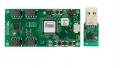
Learn more about the FRDM-K64F dev platform!
The FRDM-K64F is a development platform which utilizes the MK64FN1M0VLL12 microcontroller. This microcontroller contains an ARM Cortex-M4 core with a floating point unit. It has a maximum operating frequency of 120 MHz, 256 KB of RAM, 1 MB of flash and a host of other peripherals. It is ideal for a number of IoT applications which may utilize Ethernet, SD card storage, and the onboard analog-to-digital converters. Before we get ahead of ourselves, however, we need to get the board up and running with the development tools we are using. The easiest way to do this is to use the FRDM-K64F GPIO module to blink LEDs. This will involve first a simple demonstration of rapid prototyping using the mbed platform and then a more in-depth analysis at the register level in KEIL in which we will configure the GPIO module for both inputs and outputs.
Downloading a Blinky Example to the FRDM-K64F Using mbed
When I mentioned downloading a simple blinky example to the FRDM-K6F using the mbed platform, I mean using the mbed online IDE to do so rather than the new mbed OS. The mbed online IDE is fantastic for rapid prototyping and will be used here to test the functionality of the LEDs on the board. The ability to develop a proof of concept extraordinarily quickly using the online IDE is one of its most attractive qualities. Indeed, the number of crowdfunded projects that at least owe part of their development to rapid prototyping on the mbed platform is growing.
Updating the Firmware on the Board
Before we do anything, it is important to update the firmware on the FRDM board itself for use with mbed. Detailed instruction on how to do so, along with the latest firmware update, can be found on the Firmware FRDM K64 page of the mbed site.
For Windows, the following should be performed:
- Disconnect the board from power sources and the computer
- Hold the RESET button, located near the SDAUSB, and plug the board in via the SDAUSB.
- A drive called BOOTLOADER should mount
- Release the RESET button.
- Drag and drop the latest firmware update download onto the drive
- Once the download has completed the onboard green status LED should blink rapidly
- Disconnect and reconnect the usb cable, the board should now enumerate as MBED
Locating and Downloading the Hello World example onto the Board.
Situated on the FRDM-K64F information page on the mbed site is the mbed_blinky example as shown below:

Simply click the import program and choose an appropriate name to import the program into the online IDE. By ticking the checkbox next to Update, you can ensure that the latest libraries are used for the program.

Once imported, the program should open automatically and you will be greeted by a view of the online IDE. In the left hand column you should see the Project Workspace. The main editor window is located next to this.

The editor should display code similar to the code shown below. Here the mbed libraries have abstracted away much of the register level code and we can simply configure the pin as an output by using the DigitalOut interface, or the DigitalIn interface to configure it as an input.
#include "mbed.h"

DigitalOut myled(LED1);

int main() {
    while(1) {
        myled = 1;
        wait(0.2);
        myled = 0;
        wait(0.2);
    }
}
It is important to ensure the correct platform is selected. The platform selected is located in the top right hand corner of the IDE. To change the platform click on the currently selected platform and change to the platform required or add a new platform by browsing to the platform required and clicking add to compiler.
Simply download the program using the compile button. Locate the download and drag and drop this binary file onto the MBED drive. Press the reset button and the red LED should blink every 0.2 seconds. That’s it, the board is now setup to work with the mbed online IDE and it has been flashed with its first program!
Downloading a Blinky example to the FRDM-K64F using KEIL MDK
Of course, the simple approach provided by using the online mbed IDE has its drawbacks. As you might expect, the debug capabilities of an IDE running in a browser are not extensive. If you are going to attempt to debug using the mbed online IDE, you can only really print something to a terminal. Sometimes, however, for more complex applications, it is necessary to use a tool with a more complete set of debug resources. Stepping through code, adding breakpoints and checking registers and variable in memory is a fantastic way to debug your code. The ARM KEIL MDK provides this functionality.
Setting up the FRDM-K64F for Use With KEIL MDK
In order to set up the board for use with the KEIL MDK we must first download the appropriate driver for use with KEIL. The OpenSDA V2 driver is J-Link compatible and will be used here. The process for installing the driver is exactly the same as for installing the mbed driver as explained above. Once the driver is installed correctly the board should enumerate as JLINK.
Example Code for KEIL MDK
To create a blinky example using the KEIL MDK, we have to take a look at the registers associated with the GPIO module. Information on these can be found in the K64 Sub-Family Reference Manual, chapter 55 on page 1757.
The registers that can be accessed in regards to the GPIO module are shown in the table below:
|
Port Data Output Register (GPIOx_PDOR) |
The logic levels of a pin can be assigned to its corresponding bit. |
| Port Set Output Register (GPIOx_PSOR) | The logic level of a pin can be set to 1, regardless of its current state, by writing a 1 to the corresponding bit. |
| Port Clear Output Register (GPIOx_PCOR) | The logic level of a pin can be cleared to 0, regardless of its current state, by writing a 1 to the corresponding bit. |
| Port Toggle Output Register (GPIOx_PTOR) | The logic level of a pin can be toggled by writing a 1 to the corresponding bit. |
| Port Data Input Register (GPIOx_PDIR) | A read only register used to determine the state of a pin. |
| Port Data Direction Register (GPIOx_PDDR) | Used to configure the pins for input or output. If a zero or a one is assigned to the corresponding bit for the pin, it is an input or output respectively. |
A Brief Review of Some Important Bitwise Operations
Perhaps two of the most important operators that are performed in configuring registers are the bitwise AND assignment operator and the bitwise OR assignment operator. These can be used to set or clear a specific bit within a register without altering the rest of the register.
uint8_t myVar =00101100;
myVar |= 00000001;
myVar &=~ 00000001;
In the code above, we OR the original value with another value and assign the result to the original value to achieve the result shown equivalently below:
00101100 | 00000001 = 00101101
We then AND the original value with another, inverted, value and assign the result to the original value to achieve the result shown equivalently below:
00101101 & 11111110 = 00101100
Initializing the GPIO Module
The code for the initialisation of the GPIO module is shown below. By including the header file for the microcontroller, which is included in the KEIL libraries, we can use the defines in the header to address the appropriate registers with the appropriate values. In this code, the clocks required for the ports used are enabled. The port control register is used to assign the pin mux for each pin to "Alt 1", ie. GPIO. Finally, the bits are set as inputs or outputs depending on the function. In this case, the RGB LED is configured as an output and switch 2 is configured as an input.
#include "MK64F12.H"

void GPIO_init(void){

	SIM_SCGC5 |= SIM_SCGC5_PORTB_MASK; 		//Enable Port B Clock Gate Control
	SIM_SCGC5 |= SIM_SCGC5_PORTC_MASK;		//Enable Port C Clock Gate Control
	SIM_SCGC5 |= SIM_SCGC5_PORTE_MASK;		//Enable Port E Clock Gate Control

	/*Port Multipexing*/
	PORTB_PCR21 |= 1UL<<8;                          //Blue Led configured as Alt 1
	PORTB_PCR22 |= 1UL<<8;				//Red Led configured as Alt 1
	PORTE_PCR26 |= 1UL<<8;		                //Green Led configured as Alt 1
	PORTC_PCR6  |= 1UL<<8;		                //Switch 2 configured as Alt 1

	GPIOB_PDDR |=  (1UL << 21);		        //Set bit 21 of port B as Output
	GPIOB_PDDR |=  (1UL << 22);		        //Set bit 22 of port B as Output
	GPIOE_PDDR |=  (1UL << 26);		        //Set bit 26 of port E as Output
	GPIOC_PDDR &=~ (1UL << 6);		        //Set bit 6 of port C as Input

}
The Main Function
The code in the main function is shown below. A rudimental delay is used to test the correct configuration of the GPIO module. The code evaluates whether switch 2 is pressed by checking the appropriate bit in the GPIOx_PDIR. If it is, the LEDs blink in the sequence Red then Green then Blue. If it is not, the Red and Blue LEDs are lit constantly. In this code some different examples of turning the outputs on and off are included that use the GPIOx_PDOR, GPIOx_PSOR, GPIOx_PCOR and GPIOx_PTOR registers.
int main(void){
	uint32_t Delay = 0xFFFFF;		//Delay for blink delay
	GPIO_init();                            //Intialise the pins for GPIO

	GPIOB_PDOR |= (1UL << 22);	//Turn Off Red LED
	GPIOB_PDOR |= (1UL << 21);	//Turn Off Blue LED
	GPIOE_PDOR |= (1UL << 26);	//Turn Off Green LED

	while(1)
	{
		if(!(GPIOC_PDIR & (1UL<< 6)))		//Blink LEDs when switch is pressed
		{
			GPIOB_PDOR |= (1UL << 22);	//Turn Off Red LED
			GPIOB_PDOR |= (1UL << 21);	//Turn Off Blue LED
			GPIOE_PDOR |= (1UL << 26);	//Turn Off Green LED

			Delay = 0xFFFFF;		//Reset Delay
			GPIOB_PDOR &=~ (1UL << 22);	//Turn On Red LED
			while(Delay != 0)		//Wait Delay Value
			{
				Delay--;
			}
			Delay = 0xFFFFF;		//Reset Delay
			GPIOB_PDOR |= (1UL << 22) ;     //Turn Off Red LED
			while(Delay != 0)		//Wait Delay Value
			{
				Delay--;
			}
			Delay = 0xFFFFF;		//Reset Delay
			GPIOE_PCOR |= (1UL << 26);	//Turn On Green LED
			while(Delay != 0)		//Wait Delay Value
			{
				Delay--;
			}
			Delay = 0xFFFFF;		//Reset Delay
			GPIOE_PSOR |= (1UL << 26);      //Turn Off Green LED
			while(Delay != 0)		//Wait Delay Value
			{
				Delay--;
			}
			Delay = 0xFFFFF;		//Reset Delay
			GPIOB_PTOR |= (1UL << 21);	//Turn On Blue LED
			while(Delay != 0)		//Wait Delay Value
			{
				Delay--;
			}
			Delay = 0xFFFFF;		//Reset Delay
			GPIOB_PTOR |=  (1UL << 21);     //Turn Off Blue LED
			while(Delay != 0)		//Wait Delay Value
			{
				Delay--;
			}

		}
	else {
			GPIOB_PDOR &=~ (1UL << 22);	//Turn On Red LED
			GPIOB_PDOR &=~ (1UL << 21);	//Turn On Blue LED
		}
	}
	return 0;
}
Creating a Project in KEIL MDK and Flashing the Board
To create a new project in KEIL MDK V5, go to project >> new project. Upon creating a new project, the target device must be selected. Browse to Freescale >> K60 series and select MK64FN1M0xxx12. Note that you may have to download and install the appropriate pack from the MDK software packs page on the KEIL website.

Next the correct drivers for the project must be selected. Under "CMSIS" select "CORE" and under "Device" select "Startup".
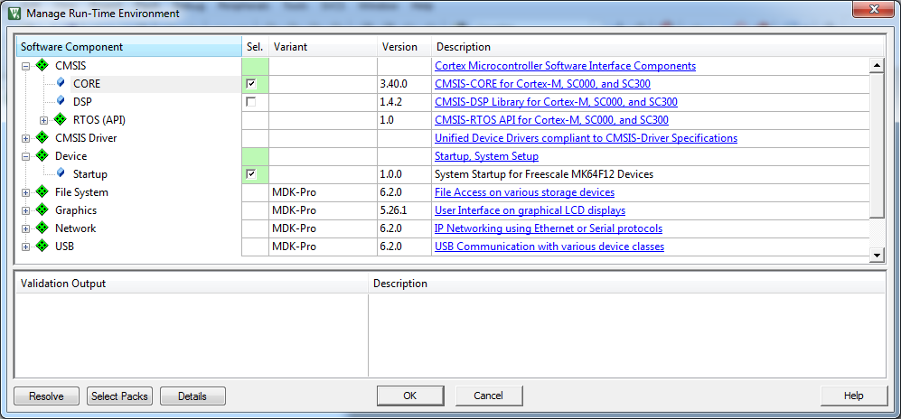
Upon completion of these steps the project successfully opens. It is necessary to save a new main file with the code outlined above and include this in the project by double clicking in the project navigation window inside “Source Group 1.”
Once this is completed, clicking the “compile all” icon in the toolbar will compile the project. Now it is time to download the program onto the board. To do this open the options for target window by clicking the little magic wand icon in the toolbar. Navigate to the Debug tab and ensure “J-LINK/ J-Trace Cortex” is selected in the use setting.

In addition to this, click the “setting” button to see more options and select the “SW” option for "Port" in the debug tab.

Now the program can finally be downloaded onto the development board. Press the load button in the build toolbar. Once you have done this, the program should download onto the board and the LEDs and switch should function as anticipated!


Only for Windows??