 Facebook
 Google
 GitHub
 Linkedin
Extend EAGLE CAD Tool with ULPs: Writing Your First User Language Program
In this tutorial, you will learn how to write your first ULP in EAGLE CAD to add a new capability to your CAD tool.
In this tutorial, you will learn how to write your first ULP in EAGLE CAD to add a new capability to your CAD tool.
A User Language Program (ULP) is a set of extensions for EAGLE CAD users to either facilitate a routine job in an automated way or do a job that can’t be done without a ULP’s help. For example, the only way to import an image to your PCB design is by using the command import-bmp ULP. Auto-placement, exporting BOM, and renumbering parts in a schematic are all routine jobs with which ULP can help.
From a developer point of view, EAGLE ULP shares a lot of similarities with C — actually, it’s a C-like language used to develop these extensions. So why is it an important programming language to learn? The main reason is to develop your own ULP to help yourself and other designers. In addition, ULPs are written mostly by hobbyists and engineers in their free time which often means very little maintenance or revisions are done in the future.
Personally, I’ve been using a ULP to produce inverted (aka negative) silkscreen on the PCB. The only available ULP on the web, negasilk (link opens zip file), can perform the job I want, but with tedious steps. Because this ULP can’t be applied to my design directly, I should run it in a new PCB file instead—copy the output, and then paste it back to the original design. Knowing the basics of ULP helped me to improve the process, making it easier for myself and others in the first place.
First Look of ULP
EAGLE User Language can be used to access the EAGLE data structures and to create a wide variety of output files.
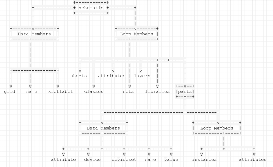
There are three main types of data structures in EAGLE: lbr, sch, and brd. I think calling them objects is more sensible because these data structures have two types of members: data members and loop members.
Data members store data such as file name, grid unit, and symbol name, while loop members are used to switch between the elements of the same object type, like a loop function for parts in a schematic file or in a library object. Each running instance member of the loop contains data members.
Are you puzzled? Don't worry, the following example will help make things clearer. The example ULP will get each part name and count the parts. Basically, to develop a ULP you need a text editor and a text file with a ulp extension.
string Names,result;
int Number=0;
schematic(S)
        {
            S.parts(P)
            {
                  Number++;
               Names+=P.name;
               Names+=",";
            }
            sprintf(result,"%d Parts, Names:%s",Number,Names);
            dlgMessageBox(result,"+OK");
        }
The output of running the previous ULP.
The schematic(S) statement is used to access the context of the schematic to reach all objects inside it respectively. S, the identifier of the schematic object, executes the code block between {..}. Schematic object (UL_SCHEMATIC object) has its own data and loop members to access other objects (parts, sheets, etc.).
As we can see, S.parts(P) is the method responsible for making a loop for each part P.

Data and loop members of the UL_SCHEMATIC object.
In a ULP manual, you can find extensive documentation about each object and its members. I will summarize them in a tree diagram.
Let’s go a step back; generally, ULP’s structure consists of declaring variables, defining functions if available, and finally the main procedures. There is no need to put the main function (void main()), although I can find some ULPs both with/without the main function. Simply, any statement after the function and variable definition is considered the main function.
Let’s modify the first example to count how many sheets the design has and how many parts are in each sheet.
string Names,result;
int Number=0,Sh_Number=0;
schematic(S)
        {
            S.sheets(Sh)
            {
                Sh_Number++;
                Sh.parts(P)
                {
                    Number++;
                    Names+=P.name;
                    Names+=",";

                }
                sprintf(result,"Sheet #%d with %d Parts, Names:%s",Sh_Number,Number,Names);
                dlgMessageBox(result,"+OK");
                Number=0;
                Names="";
            }
        }
Let’s follow this on the tree:

Passing Commands to the Editor
There are two ways to pass commands to the EAGLE editor.
The first option is to use the exit() function. This is the most forward way; it terminates the execution of ULP and passes the commands to the editor. The commands must be a string argument to this built-in function. For example, exit(“Move R1”) will make EAGLE execute this command after terminating ULP.
The second option is to create a script file that can be executed later. While scripts (.src files) are not our interest in this tutorial, it’s enough to know that scripts contain—very basically— a set of editor commands.
After ULP executes, the script file is created and you can run it using SCRIPT file_name; command or from the script icon in the menubar. Generally, using exit function is more common.
To see exit function in action, we’re going to write a simple program to add the current date to the design as a text in layer 21.
    if (library || schematic)
    {
        dlgMessageBox("! Open this ULP from PCB Editor","+OK");
        exit(-1);
    }

string Months[]= {"Jan","Feb","Mar","Apr","May","June","July","Aug","Sept","Oct","Nov","Dec"};
int t = time();
string CMD,text;

CMD = "GRID INCH;LAYER 21;";
CMD += "CHANGE SIZE 0.066;";
CMD += "CHANGE RATIO 15%;";
CMD += "CHANGE FONT VECTOR;";
sprintf(text,"TEXT '%d %s %d'",t2day(t),Months[t2month(t)],t2year(t));
CMD += text;
exit(CMD);
Let’s break the code down.
    if (library || schematic)
    {
        dlgMessageBox("! Open this ULP from PCB Editor","+OK");
        exit(-1);
    }
Library and schematic are integer constants, returning 1 if the current editor window is library or schematic, and 0 otherwise.
dlgMessageBox("! Open this ULP from PCB Editor","+OK");
This will bring a popup window with a message. We will explain in short more about dialogs in ULP.
exit(-1); Will terminate the ULP (error case).
string Months[]= {"Jan","Feb","Mar","Apr","May","June","July","Aug","Sept","Oct","Nov","Dec"};
int t = time();
string CMD,text;
This is the variables declaration.
time() function is a built-in one which returns the system time in a numerical format.
CMD = "GRID INCH;LAYER 21;";
CMD += "CHANGE SIZE 0.066;";
CMD += "CHANGE RATIO 15%;";
CMD += "CHANGE FONT VECTOR;";
These commands are used to set the grid unit to inches and to change the text size, ration, and font type. You must separate commands with semicolons.
sprintf(text,"TEXT '%d %s %d'",t2day(t),Months[t2month(t)],t2year(t));
The sprintf function is used to format the data string.
exit(CMD);The exit function will pass the CMD string onto the editor and terminate ULP execution.
Dialogs in EAGLE ULP
ULP provides a set of built-in functions for dialogs as a frontend to a User Language Program.
dlgDialog is the basic container of any other dialog object. It executes the dialogs defined by the block between the brackets {..}.
As an introduction, we are going to build a simple dialog consisting of a window with a “Hello” title and an “Ok” push button.
int Result = dlgDialog("Hello")
{
dlgLabel("Hello world");
dlgPushButton("OK")
{
dlgMessageBox("! YOU PRESSED OK!","OK");
dlgAccept();
}
};
dlgDialog has a one string argument to define the dialog title.
dlgPushButton adds a push button titled OK while dlgMessageBox shows a simple message box with an OK button. Finally, to exit the dialog dlgAccept function accepts the dialog content (no content here) and closes it.

The output of running the previous ULP.
Note: Some special characters like &,+ and - are used within the text in dialogs to do a certain job.
‘&’ Specifies hotkey to make the focus go to that object/label.
‘+’ Makes the button selected when you press Enter.
‘-’ Makes the button selected when you press Esc.
Example:
int result = dlgMessageBox("Try To Press:","+Enter","&O","-Esc");

switch(result)
{
case 0:
dlgMessageBox("YOU PRESSED OK!");
break;
case 1:
dlgMessageBox("YOU PRESSED O!");
break;
case 2:
dlgMessageBox("YOU PRESSED Esc!");
break;
}

The output of running the previous ULP.
Other dialog functions are for user input like listview, radio buttons, and data field input.
After reading the explanation of their usage, you can easily use any other dialog function. Meanwhile, there are many other functions in the same category that can be found in ULP manual.
dlgListView
dlgListView defines a multi-column listview with the contents of the given array. It takes three main arguments: the first argument is a string argument to define the header of the listview, the second argument is an array of strings to be shown as list items, and the third argument is an integer that reflects the index of the selected listview element in the array. dlgListView can contain a block of code that executes when you double click on an element.
dlgRadioButton
dlgRadioButton defines a radio button with a given text. It takes two arguments: the first argument is to use a string to define the text alongside the button, and the second argument is an integer that reflects the selected radio button from a group defined using the dlgGroup function. All radio buttons within the same group must use the same selection variable.
dlgStringEdit
dlgStringEdit defines a string entry field. It has one string argument to contain the value entered by the user. Note: It works in the same manner dlgRealEdit and dlgIntEdit work.
Let’s put the above information in action. In the following example, we are going to examine the usage of dlgListView, dlgRadioButton, and dlgStringEdit.
string Items[] = { "Item One", "Item Two", "Item Three" }, Item ;
int L_Selected = 0,R_Selected=0; // initially selects "One"
int Result = dlgDialog("Items")
{
dlgLabel("Choose One:");

dlgHBoxLayout
{
dlgListView("Name\tDescription", Items, L_Selected)
 {
dlgMessageBox("You have selected " + Items[L_Selected]);
}

dlgGroup("Items")
 {
dlgRadioButton("&One", R_Selected);
dlgRadioButton("&Two", R_Selected) {dlgMessageBox("You have selected " + Items[L_Selected]);}
dlgRadioButton("&Three", R_Selected);
}
}
dlgVBoxLayout
{
dlgLabel("Enter &Item");
dlgStringEdit(Item);
dlgPushButton("OK")
{
dlgMessageBox("You have selected from ListView " + Items[L_Selected] + ". From RadioButton " + Items[R_Selected] + ", and entered "+ Item);
dlgAccept();
}
}
};
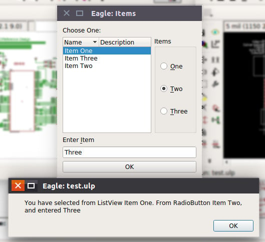
The output of running the previous ULP.
dlgListView("Name\tDescription", Items, L_Selected)As shown in the image above the listview has “Name” and “Description” header and shows the elements of items array. The selected item index will be stored in L_Selected.
If you click twice on any item of the list—the code block will execute.
dlgGroup("Items")
 {
dlgRadioButton("&One", R_Selected);
dlgRadioButton("&Two", R_Selected) {dlgMessageBox("You have selected " + Items[L_Selected]);}
dlgRadioButton("&Three", R_Selected);
}
Radio buttons must be grouped together using dlgGroup and share the same selection variable R_Selected. If you click on radio button “Two”, you will see a message and this is an example of how radio buttons can execute code.
Note: dlgHBoxLayout and dlgVBoxLayout are used to arrange the layout horizontally and vertically respectively.
Exercise
As a small exercise, you can write a simple ULP to add a proper frame using the available ones in the frames library to your schematic drawing depending on its size. I did the measurement of the frames for you to use it in this exercise. You need to scan the drawing to know its dimension.

Dimensions in Mil
To solve this exercise you will use the following skills:
- The ability to use data and loop members to get the data needed to calculate the dimension of the drawing.
- The ability to use EAGLE commands to add a device to a design.
- The ability to use dialogs in ULP.
This is a small test for my ULP to solve the exercise.


Note: Just for fun, I added an icon to the menu bar. You can do that by adding the following line, in SCH: section, to eagle.scr file located in src folder in the installation directory.
'[FrameIt.png] Add Frame : Run AddFrame.ulp;'\
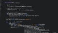
Source code
Read More
There are many other built-in constants, variables, functions, and statements in ULP besides a lot of data and loop members in data structures. After you read and understand this tutorial you should always use the well-documented ULP manual as a reference and to extend your knowledge with ULP.
If you'd like to learn more about EAGLE CAD, check out our series below:
- Easier PCB Design: Eagle CAD Tips and Tricks
- EAGLE CAD Tips and Tricks, Part 2
- EAGLE CAD Tips and Tricks, Part 3


Hello…..
how to make an ulp for the Board that only presses the image icon in the menu so that we can get the ulp we want .......
thank you?