 Facebook
 Google
 GitHub
 Linkedin
How to Use a DHT11 with a PIC16F628A and LCD
How to read humidity and temperature from a DHT11 and display it on a LCD with a PIC microcontroller. In this example we're going to use a PIC16F628A.
How to read humidity and temperature from a DHT11 and display it on a LCD with a PIC microcontroller. In this example we're going to use a PIC16F628A.
Requirements
To complete this project, you'll need the following:
- A computer with Microchip's MPLAB X IDE, with the XC8 v1.34 compiler installed. (I'm using MPLAB X v3.05 and XC8 v1.34)
- PIC16F628 microcontroller
- LCD (HD4480 or equivalent)
- DHT11 sensor
- A way to program the MCU (I'm using a PICkit3)
- Parts listed in the Partslist from Eagle.
- If you want to breadboard the circuit, you'll need a breadboard and some jumper wires.
Introduction
The DHT11 is a humidity and temperature sensor that uses one wire to send 40-bits of data. The 16 first bits are the integer and decimal of the humidity, the next 16 bits are the integer and fractions of the temperature, and the last 8 bits are the checksum.
To get the DHT11 and the MCU to talk together, they need to be synchronized. To synchronize them, the MCU sends a Start signal that is a 20us high pulse on the data pin. After the pulse, the MCU waits for the data to be received. In the software, we have to change the direction of the data pin. You can read more about the DHT11 in the datasheet. You can get the sensor in both 4-pin and 3-pin layout, but we're using the 3-pin version. There's no difference in the performance of the two, and the extra pin is not connected to anything.

Hardware
The first smart thing to do when making a gadget is to make a block diagram. This way you will get an overlook of what you want and how you want it. This is a block diagram of our gadget:

(It might be a bit overkill to make a block diagram of every little gadget you make, but I find it very useful.)
We want the DHT11 to send data to the MCU.
We want the MCU to process the data and display it on the LCD.
We want to be able to program the MCU with ICSP.
Schematic layout
The schematic layout is split into blocks:
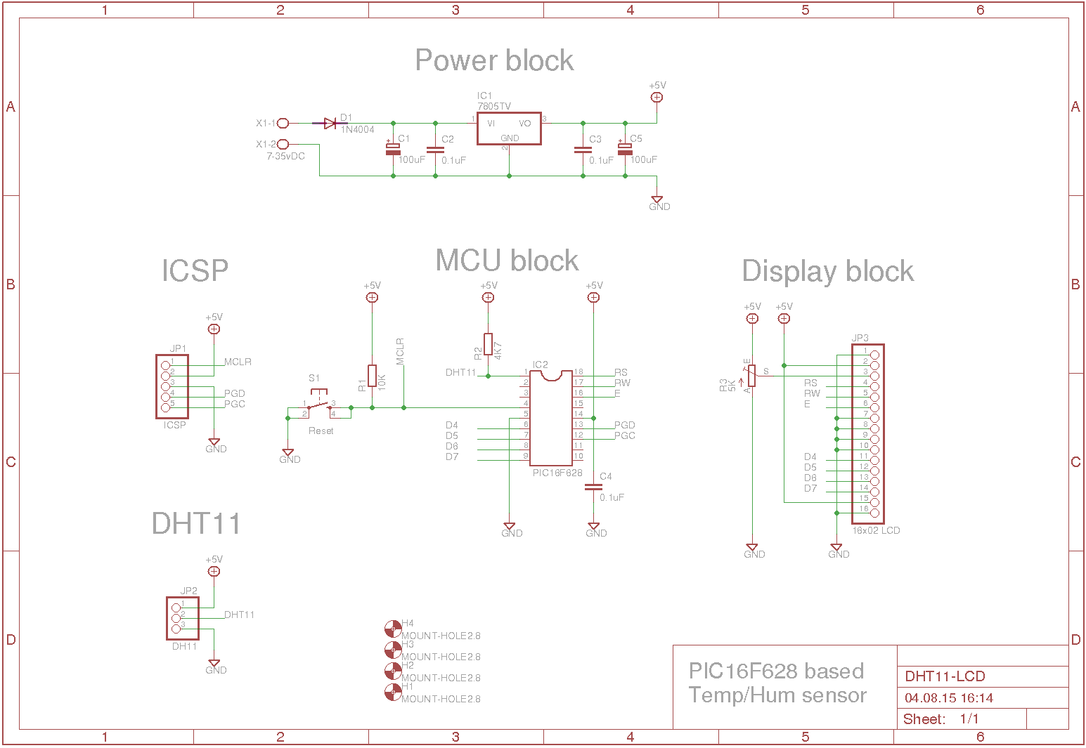
| Powerblock | Regulates the power to 5 volt. It is using the LM7805. |
| ICSP | This is a 1x5 pin header, connected to the MCU's programming pins. We use this header to program the MCU. |
| DHT11 | This is a 1x3 pin header, which holds the sensor. The middle pin is connected to the MCU, for data transfer. |
| MCU | This is the PIC16F628A, which receives data from the DHT11 and displays it on the LCD |
| Display | This is a 16x02 LCD, that displays the humidity and temperature. |
We are using the MCU's internal 4MHz oscillator. Therefore there are no crystals or ceramic resonators in the circuit.
The following is the parts list, generated from Eagle:
| Part | Value | Device | Package | Library | Sheet |
|---|---|---|---|---|---|
| C1 | 0.1uF | C-EU025-050X050 | C025-050X050 | rcl | 1 |
| C2 | 100uF | CPOL-EUE2.5-5 | E2,5-5 | rcl | 1 |
| C3 | 0.1uF | C-EU025-050X050 | C025-050X050 | rcl | 1 |
| C4 | 100uF | CPOL-EUE2.5-5 | E2,5-5 | rcl | 1 |
| C5 | 0.1uF | C-EU025-050X050 | C025-050X050 | rcl | 1 |
| D1 | 1N4004 | 1N4004 | DO41-10 | diode | 1 |
| IC2 | 7805TV | 7805TV | TO220V | linear | 1 |
| IC3 | PIC16F628 | DIL18 | DIL18 | ic-package | 1 |
| JP1 | ICSP | PINHD-1X5 | 1X05 | pinhead | 1 |
| JP2 | 16x02 LCD | PINHD-1X16 | 1X16 | pinhead | 1 |
| JP3 | DHT11 | PINHD-1X3 | 1X03 | pinhead | 1 |
| R1 | 10K | R-EU_0204/7 | 0204/7 | rcl | 1 |
| R2 | 5K | TRIM_EU-LI10 | LI10 | pot | 1 |
| R3 | 4K7 | R-EU_0204/7 | 0204/7 | rcl | 1 |
| S1 | Reset | TAC_SWITCHPTH | TACTILE-PTH | SparkFun | 1 |
| X1 | 7-35vDC | W237-10 | W237-102 | con-wago-500 | 1 |
Now that the hardware is good, it's time for the software.
Software
When you installed the XC8 compiler, you also installed some header and source files. In this How-To we're using the LCD files that comes with the XC8 compiler: the XLCD.H and a bunch of source files. To make things a bit easier I've copied all the source files into one file. On my Ubuntu installation I find the XLCD sourcefiles under:
/opt/microchip/xc8/v1.34/sources/pic18/plib/XLCD
There are 10 files there, bysyxlcd.c, openxlcd.c, putrxlcd.c and so on. I placed all these files in one file, and I called it my_xlcd.c. This files now hold all the functions. myxlcd.c file and the xlcd.h file is copied to the project folder. (The xlcd.h file is found here: /opt/microchip/xc8/v1.34/include/plib). The xlcd.h file is a standard file that needs a little bit of editing. We need to change the connections for the MCU's pins to match our setup:
/* DATA_PORT defines the port to which the LCD data lines are connected */
 #define DATA_PORT      		PORTB
 #define TRIS_DATA_PORT 		TRISB

/* CTRL_PORT defines the port where the control lines are connected.
 * These are just samples, change to match your application.
 */
 #define RW_PIN   PORTAbits.RA0   		/* PORT for RW */
 #define TRIS_RW  TRISAbits.TRISA0    	/* TRIS for RW */

 #define RS_PIN   PORTAbits.RA1  		/* PORT for RS */
 #define TRIS_RS  TRISAbits.TRISA1    	/* TRIS for RS */

 #define E_PIN    PORTAbits.RA7 		/* PORT for D  */
 #define TRIS_E   TRISAbits.TRISA7    	/* TRIS for E  */
Here, the connection between the LCD and the MCU is defined. There is nothing more to to with these two files. (my_xlcd.h and my_xlcd.c)
Next is the main program. It starts off with some includes, configuration bits, defines, variables and prototyping of the functions to come:
// INCLUDES
#include                // Including Standard Input / Outputlibrary
#include               // Including Standard library function
#include                   // Including XC8 compiler library
#include "my_xlcd.h"            // Including my custom LCD

// CONFIG
#pragma config FOSC = INTOSCIO  // Oscillator Selection bits (INTRC oscillator: I/O function on RA6/OSC2/CLKOUT pin, I/O function on RA7/OSC1/CLKIN)
#pragma config WDTE = OFF       // Watchdog Timer Enable bit (WDT disabled)
#pragma config PWRTE = ON       // Power-up Timer Enable bit (PWRT enabled)
#pragma config MCLRE = ON       // RA5/MCLR pin function select (RA5/MCLR pin function is MCLR)
#pragma config BOREN = ON       // Brown-out Reset Enable bit (BOD Reset enabled)
#pragma config LVP = ON         // Low-Voltage Programming Enable bit (RB4/PGM pin has PGM function, low-voltage programming enabled)
#pragma config CPD = OFF        // Data Code Protection bit (Data memory code protection off)
#pragma config CP = OFF         // Code Protection bits (Program memory code protection off)

// DEFINES
#define _XTAL_FREQ 4000000          // Telling the compiler, that we are using 4MHz
#define data PORTAbits.RA2          // Defining RA0 as datapin
#define data_dir TRISAbits.TRISA2   // Definig TRISA0 as dataport

// GLOBAL VARIABLES
char message1[] = "Temp = 00.0 c";
char message2[] = "RH   = 00.0 %";
unsigned short TOUT = 0, CheckSum, i;
unsigned short T_Byte1, T_Byte2, RH_Byte1, RH_Byte2;

// PROTOTYES
void init_XLCD(void);
void DelayFor18TCY(void);
void DelayPORXLCD(void);
void DelayXLCD(void);
void Delay10KTCYx(unsigned char);
void StartSignal(void);
unsigned short ReadByte();
unsigned short CheckResponse();
Then we have the functions. To get the LCD to work with our MCU, we need to make a few Delay functions. In the top of your XLCD.H file it is stated that:
* - The user must provide three delay routines:
* - DelayFor18TCY() provides a 18 Tcy delay
* - DelayPORXLCD() provides at least 15ms delay
* - DelayXLCD() provides at least 5ms delay
We need to add a fourth delayfunction, Delay10KTCYx
Here is the LCD's init function and the delay functions:
// FUNCTIONS
void init_XLCD(void){
    OpenXLCD(FOUR_BIT & LINES_5X7);     // Sets 4-bit & 5x7 charachters
    while(BusyXLCD());                  // Checks if LCD is busy
    WriteCmdXLCD(0x06);                 // Moves cursor right
    WriteCmdXLCD(0x0C);                 // Display on, cursor off
}

void DelayFor18TCY(void){               // as it says in the XLCD.H file
    NOP(); NOP(); NOP(); NOP(); NOP(); NOP(); NOP();
    NOP(); NOP(); NOP(); NOP(); NOP(); NOP(); NOP();
    return;
}

void DelayPORXLCD(void){               // as it says in the XLCD.H file
    __delay_ms(15);
}

void DelayXLCD(void){                 // as it says in the XLCD.H file
    __delay_ms(5);
}

void Delay10KTCYx(unsigned char){     // as it says in the XLCD.H file
    __delay_ms(10);
}
Next in line are the Start signal, the Readbyte, and the CheckResponse functions:
void StartSignal(){
    data_dir = 0;       // Sets TRISA2 to output
    data = 0;           // Set RA2 to LOW
    __delay_ms(18);     // Waits for 18 ms
    data = 1;           // Sets RA2 HIGH
    __delay_us(20);     // Waits for 20 ms
    data_dir = 1;       // Sets TRISA2 to input
}

unsigned short ReadByte(){
    unsigned short num = 0, t;
    data_dir = 1;                       // Sets TRISA2 to input
    for (i=0;i<8;i++){                  // Start loop
        while(!data);                   // When data is not valid
        TMR2 = 0;                       // Sets TMR2 to 0
        T2CONbits.TMR2ON = 1;           // Start TMR2 from 0 when a low to high data pulse
        while(data);                    // is detected, and wait until it falls low again
        T2CONbits.TMR2ON = 0;           // Stop the TMR2 when the data pulse falls low
        if(TMR2>40) num |= 1 << (7-i);  // If time > 40us, data is 1
        }
    return num;                         // Return 8-bit = 1-byte
}

unsigned short CheckResponse(){
    TOUT = 0;
    TMR2 = 0;
    T2CONbits.TMR2ON = 1;       // Turn on TMR2
    while(!data && !TOUT);      // While NOT data and NOT TOUT
    if (TOUT) return 0;         // Return 0 => OK
    else {
        TMR2 = 0;               // Disable Timer 2
        while(data && !TOUT);   // While data and NOT TOUT
        if(TOUT) return 0;      // If Tout = 1 then return 0 => OK
        else {
            T2CONbits.TMR2ON = 0;   // Turn off TMR2
            return 1;               // Return 1 => NOT OK
        }
    }
}
To get hold of when the MCU is sending the Start signal, and when the DHT11 is finished with its 40-bit, we need an interrupt function:
void interrupt tc_int(void){
    if(PIR1bits.TMR2IF){            // If TMR2 to PR2 match Interrupt Flag
        TOUT = 1;
        T2CONbits.TMR2ON = 0;       // Stop timer
        PIR1bits.TMR2IF = 0;        // Clear TMR0 interrupt flag
    }
}
And in the end we need the main program:
int main(int argc, char** argv) {
    unsigned short check;
    TRISB = 0b00000000;         // TRISB output
    PORTB = 0b00000000;         // PORTB low
    TRISA = 0b00000001;         // TRISA output
    PORTA = 0b00000000;         // PORTA low

    CMCON = 0x07;               // Comparators off

    // TIMER
    INTCONbits.GIE = 1;         // Enable global interrupt
    INTCONbits.PEIE = 1;        // Enable peripheral interrupt
    PIE1bits.TMR2IE = 1;        // Enable Timer2 interrupt
    T2CON = 0;                  // Prescaler 1:1 and Timer2 is off initially
    PIR1bits.TMR2IF = 0;        // Clear TMR INT flag bit
    TMR2 = 0;

    init_XLCD();                // Initialize the LCD
    putrsXLCD("  Hello World.");    // Welcome text
    SetDDRamAddr(0x40);             // Move cursor to line 2
    putrsXLCD("  I'm alive.");
    __delay_ms(250);
    do {
        __delay_ms(1000);
        StartSignal();              // Send the Startsignal
        check = CheckResponse();    // Assign check with 0 = OK, or 1 = NOT OK
        if(!check) {                // OK check = 1 => NOT OK
            WriteCmdXLCD(0x01);     // Clear screen, set cursor in 0,0
            putrsXLCD("No response.");  // Write error message
            SetDDRamAddr(0x40);
            putrsXLCD("Please check.");
            }
        else {                      // IF chack = 0 => OK

        RH_Byte1 = ReadByte();      // Read first byte
        RH_Byte2 = ReadByte();      // Read second byte
        T_Byte1 = ReadByte();       // Read third byte
        T_Byte2 = ReadByte();       // Read fourth byte
        CheckSum = ReadByte();      // Read checksum
        // Checks if all bytes is equal to the checksum
        if (CheckSum == ((RH_Byte1 + RH_Byte2 + T_Byte1 + T_Byte2) & 0xFF))
        {
            message1[7] = T_Byte1/10 + 48;      // Extract the tens place
            message1[8] = T_Byte1 + 48;      // Extract the ones place
            message1[10]= T_Byte2/10 + 48;      // Extract the decimal
            message1[11] = 223;                 // ASCII code for degree symbol
            message2[7] = RH_Byte1/10 + 48;     // Extract the tens place
            message2[8] = RH_Byte1 + 48;     // Extract the ones place
            message2[10] = RH_Byte2/10 + 48;    // Extract the decimal

            WriteCmdXLCD(0x01);
            putrsXLCD(message1);    // Write the temp to LCD
            SetDDRamAddr(0x40);
            putrsXLCD(message2);    // Write the humidity to LCD
        }
        else {                      // Checksum is not correct
            WriteCmdXLCD(0x01);
            putrsXLCD("Checksum error!");
            SetDDRamAddr(0x40);
            putrsXLCD("Please wait.");
        }
        }
    } while (1);    // Do it forever.
}
This is one way to use the DHT11 with a PIC and a LCD.
Conclusion
We used a PIC16F628A MCU with this DHT11, and we displayed the temperature and humidity on a LCD. You can, with some effort, convert/adjust the code to suit your favorite MCU. The program takes up 32% of the MCU's Data memory and 55% of its Program memory. That is because the IC is small mid-range.
One of the differences between the PIC16F628 and the PIC16F628A is that the "A" version have an internal oscillator. The version without the "A" needs an external crystal or other RC network. If you buy a PIC16F628, be sure it is the "A" version. The other one is obsolete.
Pictures and Video


Give this project a try for yourself! Get the BOM.
Related Content


The PIC16F628 is a known part number that is long-since discontinued by Microchip but still available on eBay and other sites. It would be a shame if someone ordered that part instead of the part you intended for them to use - PIC16F628A. There is no on-board oscillator for the part number without “A” at the end. The part with the “A” has an on-board oscillator and is the part you intended since there is no external crystal or RC network in your circuit. It would be nice if you update your circuit parts list or make some mention of it in the text.
Hello, i m read humidity and temperature from a DHT11 and display it on a UART terminal with a PIC microcontroller(PIC16f1829).But out put is only “No response from the sensor,” plz. fined error this code.
#include
#include<stdlib.h>
#include<stdio.h>
#define _XTAL_FREQ 32000000
#pragma config FOSC = INTOSC
#pragma config WDTE = OFF // Watchdog Timer Enable bit (WDT enabled)
#pragma config PWRTE = OFF // Power-up Timer Enable bit (PWRT disabled)
#pragma config BOREN = ON // Brown-out Reset Enable bit (BOR enabled)
#pragma config LVP = OFF // Low-Voltage (Single-Supply) In-Circuit Serial Programming Enable bit (RB3 is digital I/O, HV on MCLR must be used for programming)
#pragma config CPD = OFF // Data EEPROM Memory Code Protection bit (Data EEPROM code protection off)
#pragma config WRT = OFF // Flash Program Memory Write Enable bits (Write protection off; all program memory may be written to by EECON control)
#pragma config CP = OFF // Flash Program Memory Code Protection bit (Code protection off)
#pragma config PLLEN = ON // PLL Enable (4x PLL disabled)
char message1[] = “Temp = 00.0 C”;
char message2[] = “RH = 00.0 %”;
unsigned short TOUT = 0, CheckSum, i;
unsigned short T_Byte1, T_Byte2, RH_Byte1, RH_Byte2;
void InitUART(void)
{
TRISC4 = 0; // TX Pin
TRISC5 = 1; // RX Pin
SPBRG = ((_XTAL_FREQ/16)/9600) - 1;
BRGH = 1; // Fast baudrate
//BRG16 = 0;
SYNC = 0; // Asynchronous
SPEN = 1; // Enable serial port pins
CREN = 1; // Enable reception
SREN = 0; // No effect
TXIE = 0; // Disable tx interrupts
TX9 = 0; // 8-bit transmission
RX9 = 0; // 8-bit reception
TXEN = 0; // Reset transmitter
TXEN = 1; // Enable the transmitter
}
void SendByteSerially(unsigned char Byte) // Writes a character to the serial port
{
// wait for previous transmission to finish
while(!TXIF);
TXREG = Byte;
//Lcd_Write_Char('Y');
}
unsigned char ReceiveByteSerially(void) // Reads a character from the serial port
{
if(OERR) // If over run error, then reset the receiver
{
CREN = 0;
CREN = 1;
}
while(!RCIF); // Wait for transmission to receive
return RCREG;
}
void SendStringSerially(const unsigned char* st)
{
while(*st)
SendByteSerially(*st++);
}
void StartSignal(){
TRISA&=~0x01;
PORTAbits.RA0 = 0; // Data port is output
__delay_ms(25);
PORTAbits.RA0 = 1;
__delay_us(40);
TRISA|=0x01; // Data port is input
}
unsigned short CheckResponse(){
TOUT = 0;
TMR2 = 0;
TMR2ON = 1; // start timer
while(!PORTAbits.RA0 && !TOUT);
if (TOUT) return 0;
else {
TMR2 = 0;
while(PORTAbits.RA0 && !TOUT);
if (TOUT) return 0;
else {
TMR2ON = 0;
return 1;
}
}
}
unsigned short ReadByte(){
unsigned short num = 0, t;
TRISA|=0x01;
for (i=0; i<8; i++){
while(!PORTAbits.RA0);
TMR2 = 0;
TMR2ON = 1;
while(PORTAbits.RA0);
TMR2ON = 0;
if(TMR2 > 40) num |= 1<<(7-i); // If time > 40us, Data is 1
}
return num;
}
void interrupt ISR(){
if(TMR2IF){
TOUT = 1;
TMR2ON = 0; // stop timer
TMR2IF = 0; // Clear TMR0 interrupt flag
}
}
void main() {
unsigned short check;
int buf;
APFCON0=0x84;//Alternate function enable for TX RX
ANSELA&=~0x01;//Digital select RA2
OPTION_REG|=0x80;
OSCCON=0x70;//Internal Oscillator frequency selec
InitUART();
__delay_ms(100);
SendStringSerially("start");
TMR2IE = 1; // Enable Timer2 interrupt
T2CON = 0; // Prescaler 1:1, and Timer2 is off initially
TMR2IF =0; // Clear TMR INT Flag bit
TMR2 = 0;
GIE = 1; //Enable global interrupt
PEIE = 1; //Enable peripheral interrupt
do {
__delay_ms(1000);
StartSignal();
check = CheckResponse();
if (!check) {
SendStringSerially("No response ");
SendStringSerially("from the sensor");
SendStringSerially(",\r\n");
}
else
{
RH_Byte1 = ReadByte();
RH_Byte2 = ReadByte();
T_Byte1 = ReadByte();
T_Byte2 = ReadByte();
CheckSum = ReadByte();
// Check for error in Data reception
if (CheckSum == ((RH_Byte1 + RH_Byte2 + T_Byte1 + T_Byte2) & 0xFF))
{
message1[7] = T_Byte1/10 + 48;
message1[8] = T_Byte1 + 48;
message1[10] = T_Byte2/10 + 48;
message2[7] = RH_Byte1/10 + 48;
message2[8] = RH_Byte1 + 48;
message2[10] = RH_Byte2/10 + 48;
message1[11] = 223; // Degree symbol
buf=atoi(message1);
SendStringSerially(buf);
SendStringSerially("\r\n");
buf=atoi(message2);
SendStringSerially(buf);
SendStringSerially("\r\n");
}
else{
SendStringSerially("Trying Again ...");
SendStringSerially("\r\n");
SendStringSerially("Checksum Error!");
SendStringSerially("\r\n");
}
}
}while(1);
}