Facebook
 Google
 GitHub
 Linkedin
Create a Laser Detection System Using a PICAXE
Lasers are plentiful, inexpensive, and fun to use. Here's a target that reacts when it's hit by a laser beam.
Lasers are plentiful, inexpensive, and fun to use. Here's a target that reacts when it's hit by a laser beam.
The Mighty PICAXE
This project uses a PICAXE microcontroller, and if you already know and love the PICAXE, just skip over this section. But if you are new to PICAXEs, check out the introductory articles available on AAC. A list of the author's other articles includes lots of PICAXE projects in addition to a tutorial series. You can learn to program microcontrollers, and once you do, you'll be amazed at the uses you can think of for them!
Introduction
This project describes the construction of a small target that reacts very quickly when struck by a beam of laser light, and a primary application is shooting practice. Laser inserts are available for a variety of firearms; properly installed, the laser emits a short burst of light whenever the trigger of the gun is pulled. In addition, there are toy guns that fire laser beams, and a home-built target for them can add to the fun. Of course, there are commercially available laser targets, but they can be quite expensive, and a much less costly option is presented here.
Applications for the basic circuit described in this article go beyond the shooting sports; remote control and security are two possibilities that come to mind. Perhaps this project will stimulate your "creative juices" to find even more uses for a laser target.
Warning! Although this project is intended for use with low-power lasers like those used in laser pointers, you should follow all applicable safety precautions to protect your eyes and the eyes of others. If you are using the target with a laser-equipped firearm, you should follow all safe gun handling practices.
The Actual Target
A phototransistor is one type of electronic component that responds to light. The photograph below shows a phototransistor mounted on a small (42mm x 42mm) piece of perfboard, and equipped with a pair of wires to connect it to the control circuitry. You may choose to mount the phototransistor differently in order to suit your intended usage.

The Circuit
The schematic diagram for the entire circuit is shown below; as you can see, the design is quite simple. A PICAXE microcontroller is the "brain" for the system; J1, R1, and R2 form the programming interface for the PICAXE.
In operation, U1 lights LED2 to indicate that the user should fire at the target; the time that LED2 stays lit is adjusted with VR2. Q1, the phototransistor, is connected in a voltage divider arrangement with VR1. This provides a way to adjust the sensitivity of Q1 so that it does not trigger on ambient light. Q2 is a MOSFET switch with its drain connected to pinC.3 of the PICAXE microcontroller.
When the laser light strikes Q1, it brings the gate of Q2 high, which brings pinC.3 low, and signals that the target has been hit. The PICAXE turns LED2 off and lights LED1 to provide a visual indication of the hit. After a short time (programmable,) U1 turns LED1 off and the cycle repeats for as long as the circuit is powered.

Construction
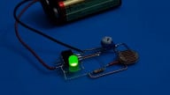
Construction of the circuit is shown below on a solderless breadboard. Note that the phototransistor is included on the breadboard in the photo, but can be removed for remote location. The wire colors shown in the photograph agree with the designations on the schematic diagram. The entire circuit should be powered by a regulated, filtered 5VDC supply.

Pinouts for Q1 and Q2 are shown below.

Details for building the remote sensor are depicted below. Be careful to connect the emitter and collector as shown in the left photo; the emitter is connected to the green wire and the collector is connected to the red wire.
As you see in the right photo, a fresnel lens has been added to the assembly. This lens effectively increases the size of the target area; without the lens, the laser pulse must strike the small surface area of the phototransistor. The lens increases the size of the target area from about 5mm to 28mm in diameter.

Component List
The components needed are shown in the table below. You will also need a regulated and filtered 5VDC power source, a solderless breadboard, and assorted wire and hardware.
| Reference No. | Description | Qty. | Source | Part No. |
|---|---|---|---|---|
| J1 | Jack, 3.5mm, 3 Conductor | 1 | Digi-Key | CP1-3533NG-ND |
| C1 | Capacitor, Ceramic, 50V, .1uF | 1 | Digi-Key | 399-9797-ND |
| R1 | Resistor, .25W, 22kOhms | 1 | Digi-Key | 22KQBK-ND |
| R2, R3 | Resistor, .25W, 10kOhms | 2 | Digi-Key | 10KQBK-ND |
| R4, R5 | Resistor, .25W, 330Ohms | 2 | Digi-Key | 330QBK-ND |
| LED1 | Diode, Light Emitting, T1 3/4, Blue | 1 | Jameco | LVB3330 |
| LED2 | Diode, Light Emitting, T1 3/4, Green | 1 | Jameco | LG3330 |
| Q1 | Transistor, Photo, T1 3/4 | 1 | Digi-Key | TEPT5600 |
| Q2 | Transistor, MOSFET, N Channel, TO92 | 1 | Jameco | BS170 |
| VR1 | Resistor, Variable,100kOhms | 1 | Digi-Key | 3362R-104LF-ND |
| VR2 | Resistor, Variable, 10kOhms | 1 | Digi-Key | 3362R-103LF-ND |
| U1 | Microcontroller, PICAXE 08M2 | 1 | P.H. Anderson.com | PICAXE-08M2 |
The Code
The code is shown below; like the circuit, it is simple, well commented, and should be easy to understand. Note that you may change the timing of the shooting sequence in lines 25, 31, 37, and 40. Remember that the times are in milliseconds.

Adjustments and Operation
Once assembled, there are only two adjustments required; follow the steps below.
- Power down the circuit.
- Turn VR1 fully counter-clockwise. This sets the sensitivity of Q1 to its minimum.
- Turn VR2 fully clockwise. This sets the shoot time to its maximum.
- Power up the circuit.
- Wait for the green LED to light.
- While the green LED is lit, turn VR1 clockwise until the blue LED lights, and then turn VR1 slightly counter-clockwise. This sets the sensitivity of Q1 to just ignore the ambient light.
- Power down the circuit.
Following is the sequence of operation.
- Power up the circuit.
- Wait for the green LED to light.
- While the green LED is lit, point the laser beam at Q1. The green LED should go out and the blue LED should light to indicate a hit. After a few seconds (determined by the code,) the blue LED should go out, and the green LED should light, which begins the cycle again.
If Q1 is too sensitive, turn VR1 counter-clockwise. If the shoot time is too long, turn VR2 counter-clockwise. Remember that timing limits are set in the code.
What Else Can You Do?
If all you want is a laser activated target to practice and play with, you're done. Have fun!
If you want to do more, remember that the PICAXE can control lots of things besides LEDs. It can actuate solenoids, motors, servos, and pretty much anything electrical. Don't forget that you can add more targets, and improve the code to provide for two shooters. You can add a scoreboard, bells, sound effects, and lots of things to increase the fun or the utility. That's the magic of microcontrollers; not even the sky is the limit!
Give this project a try for yourself! Get the BOM.