Facebook
 Google
 GitHub
 Linkedin
How to Use the Arduino’s Digital I/O
The digital inputs and outputs (digital I/O) on the Arduino are what allow you to connect sensors, actuators, and other ICs to the Arduino . Learning how to use the inputs and outputs will allow you to use the Arduino to do some really useful things, such as reading switch inputs, lighting indicators, and controlling relay outputs.
The digital inputs and outputs (digital I/O) on the Arduino are what allow you to connect the Arduino sensors, actuators, and other ICs. Learning how to use them will allow you to use the Arduino to do some really useful things, such as reading switch inputs, lighting indicators, and controlling relay outputs.
Digital signals
Unlike analog signals, which may take on any value within a range of values, digital signals have two distinct values: HIGH (1) or LOW (0). You use digital signals in situationswhere the input or output will have one of those two values. For example, one way that you might use a digital signal is to turn an LED on or off.
Functions
The Arduino functions associated with digital signals that we will be using in this tutorial are:
- pinMode()
- digitalRead()
- digitalWrite()
pinMode (pin_number, mode)
Because the Arduino digital I/O pins can be used for either input or output, you should first configure the pins you intend to use for digital I/O with this function. pin is thenumber of the pin you wish to configure. mode must be one of three values: INPUT, OUTPUT, our INPUT_PULLUP. When mode is set to INPUT_PULLUP, a 20 kohm pullup resistor is internally connected to the pin to force the input HIGH if there is nothing connected to the pin.
digitalWrite(pin_number,value)
This function writes a digital value to a pin. pin specifies which Arduino pin the digital value will be written to, and value is the digital value to which the pin is set. valuemust be either HIGH or LOW.
digitalRead(pin_number)
This function reads a digital value from a pin. pin is the number of the digital I/O pin you want to read. This function returns one of two values: HIGH or LOW.
Experiment 1: Blinking LED using delay
In this experiment, we will be switching an LED on and off using a digital output.
Hardware Required
- 1 x LED
- 1 x 220 ohm resistor
- 1 x Arduino UNO
- 1 x breadboard
- 2 x jumper Wires
Wiring Diagram

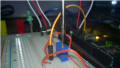
The figure above shows how to connect the LED and the 220 ohm resistor to the Arduino. As shown, the LED connects to digital I/O pin 8 of the Arduino through the resistor. The resistor controls the current through the LED. The program below first configures pin 8 to be an OUTPUT, then sets the digital I/O pin to HIGH for 1000 ms, then to LOW for another 1000 ms.
Program for Experiment #1
const int led  =  8;     //use digital I/O pin 8
void setup()
{
pinMode(led,OUTPUT);   //set pin 8 to be an output output
}

void loop()
{
   delay(1000);   	     //delay 1000 milliseconds
   digitalWrite(led,HIGH);   //set pin 8 HIGH, turning on LED
   delay(1000);   	     //delay 1000 milliseconds
   digitalWrite(led,LOW);    //set pin 8 LOW, turning off LED
}Running the experiment
-
Connect the anode of the LED to one end of the resistor and the other end of the resistor to digital I/O pin 8 on the Arduino board.
-
Connect Arduino GND pin to the cathode of the LED.
Connect the Arduino to the PC using Arduino USB cable and transfer the program to Arduino using Arduino IDE software.
-
Provide power to the Arduino board using a power supply, battery, or USB cable.
-
LED should start to blink.
Experiment 2: Blinking LED using Button
This experiment will not only demonstrate how to use a digital output, but also a digital input. Pressing a pushbutton connected to a digital input will turn an LED on or off. The program uses both the digitalWrite() and digitalRead() functions.
Hardware Required
- 1 x LED
- 2 x 220 ohm resistor
- 1x pushbutton switch
- 1 x Arduino UNO
- 1 x breadboard
- 6 x jumper Wires
Wiring Diagram
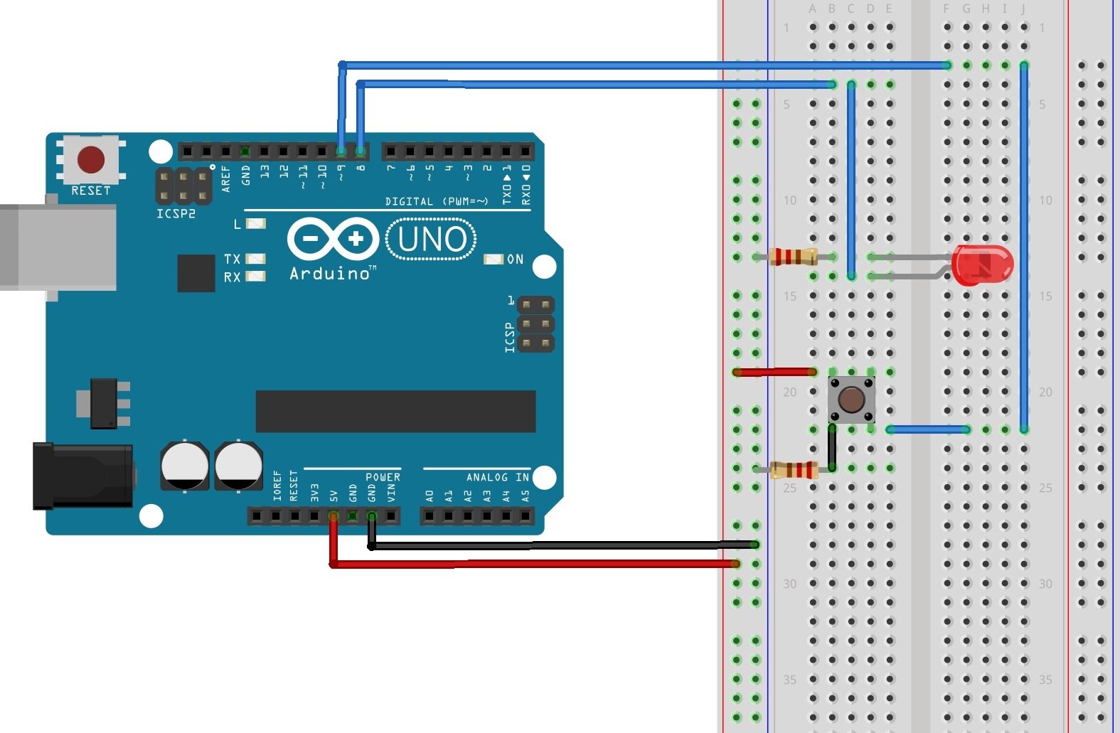
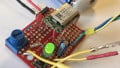
As you can see from the diagram above, we are now using two Arduino digital I/O pins. An LED is connected to pin 8, which is configured as an OUTPUT. A pushbutton is connected to pin 9, which is configured as an INPUT. When someone presses the pushbutton switch, pin 9 is set to HIGH, and the program will then set the output of pin 8 to HIGH and turning on the LED. Releasing the pushbutton resets pin 9 to LOW. The program then sets pin 8 to LOW, which turns off the LED.
Code
const int led    =   8; 	//name pin 8 as led
const int button =   9;		//name pin 9 as button
void setup()
{
pinMode(led,OUTPUT);		//set pin 8 as OUTPUT
pinMode(button,INPUT)  ;	//set pin 9 as INPUT
}
void loop()
{
   int reads = digitalRead(button);	//read the digital value on pin 9
   digitalWrite(led,reads);		//set the digital output value of pin 8 to that value
}Running the experiment
- Connect the circuit as shown in the diagram.
- Connect the Arduino using Arduino USB cable and program to Arduino using Arduino IDE software.
- Provide power to the Arduino board using a power supply, battery or USB cable.
- Press the button to turn the LED on. Release the button to turn the LED off.
Videos
Give this project a try for yourself! Get the BOM.
Related Content