 Facebook
 Google
 GitHub
 Linkedin
Make a Wireless Thermometer with PICAXE
Got some time and need a wireless thermometer? In this article I'll show you how to make such a thing with a few PICAXEs.
Got some time, and need a wireless thermometer? In this article I'll show you how to make such a thing, with a few PICAXEs.
Requirements
To complete this project, you'll need the following:
- A computer running PICAXE editor, or similar IDE to program the PICAXEs.
- Programming cable. I'm using the AXE-027.
- A PICAXE 20m2, and a 08m2.
- An LCD, an LM34, 433MHz TX and RX modules.
- Breadboards, and jumperwires.
- Parts from list below:
Parts list
Transmitter |
Receiver |
| Part | Value | Part | Value |
| C1 | 0.1 uF | C1 | 0.1 uF |
| C2 | 100 uF | C2 | 100 uF |
| C3 | 100 uF | C3 | 100 uF |
| C4 | 0.1 uF | C4 | 0.1 uF |
| C5 | 0.1 uF | C5 | 0.1 uF |
| C6 | 0.1 uF | C6 | 0.1 uF |
| D1 | 1N4004 | D1 | 1N4004 |
| IC1 | 78L05Z | IC1 | PICAXE-20M2/20X2-DIL |
| IC2 | LM340LZ-05 | IC2 | 78L05Z |
| IC3 | PICAXE-08M2-DIL | JP1 | 8-35v |
| JP1 | 12v | JP2 | AXE-027 |
| JP3 | 433MHz RF | JP3 | 433 RF RX |
| JP4 | AXE-027 | JP4 | 16x2 LCD |
| R1 | 22K | R1 | 10K |
| R2 | 10K | R2 | 5K |
| R3 | 1K | R3 | 22K |
| R4 | 10K | ||
| R5 | 22K | ||
| T1 | BC547 |
Introduction
In this article I'll make a wireless thermometer using the LM 34 temperature sensor. From the datasheet:
"The LM34 series devices are precision integratedcircuit temperature sensors, whose output voltage is linearly proportional to the Fahrenheit temperature. The LM34 device has an advantage over linear temperature sensors calibrated in degrees Kelvin, because the user is not required to subtract a large constant voltage from its output to obtain convenient Fahrenheit scaling. The LM34 device does not require any external calibration or trimming to provide typical accuracies of +-1/2o F at room temperature and +-1-1/2o F over a full range -50o F to 300o F temperature range."
This will be perfect for my project.
To read the voltage from the LM34, I'm using a PICAXE 08m2. This is a great little microcontroller. The temperature is transmitted with a RF 433MHz module. On the receiver side, I'm going to have a PICAXE 20m2, with an LCD.
Hardware
For this project, I'll be needing two circuits: one for transmitting and one for receiving. Let's start with the transmitter:

The microcontroller turns the 433MHz module on/off, with the help of a BC547 NPN transistor. This way, I do not interfere too much with other wireless applications. The transmittermodule is connected to 12v. This will increase the range.
The receiver:

Software
We need two programs: one for transmitting and one for receiving. You can download both from the links below. The sourcecode is commented at the right points, but here's some explanations of some of the commands.
In the transmitter:
readadc10 adc_pin, adc_raw
readadc10 - This is a command that takes two arguments, channel and a variable. Channel is the pin of an analog device. In my case, it's the output pin of the LM34. The variable is a wordvariable. I named my adc_raw. Readadc10 has a 10-bit resolution.
serout tx_pin, baud, ("LM34", b0, b1, b10)
serout - This command transmits serial data, 8 bit, no parity, 1 stop bit. It takes three arguments: pin, baudmode and data. Pin is the transmitting pin, which I've named tx_pin. Baudmode is set to N2400_4, and the data in my program is adc_raw in byte format. When working with word varables in the PICAXE environment, a word variable consists of two byte variables. Read more about variables in the PICAXE manuals. I've used a qualifier with the serout command. My qualifier is "LM34". With this feature, I can have different sensors or devices reporting, and the qualifiers will be sorted out by the receiver.
In the receiver:
serin rx_pin, baud, ("LM34"), b6, b7, b27
serin - This command receives serial data. It takes four or more arguments. Rx_pin is the receiving pin on the PICAXE 20m2, baud is the baudrate, ("LM23") is a qualifier, which means that everything that is received after LM34, will be read into variables. Serin read one byte at the time, and I need to put the bytes in variables.
To convert the received bytes to acsii characters. I'm using the bintoascii command:
bintoascii tmp_c, b2, b3, b4
This command converts a wordvariable to separate byte values.
Download
Download the source files, and have fun!
jc_20m2-WirelessThermometer.zip
Conclusion
In this articel, I've made a wireless thermometer with two PICAXEs: an 08M2 and a 20M2. The temperature reading side has an LM34 Fahrenheit temperature sensor. The output of this sensor is read by a microcontroller, and transmitted with a wireless module. The receiver reads the serial data, calculates both Fahrenheit and Celcuis, and finally displays the temperatures on an LCD.
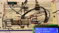
Pictures and video
Transmitter:

Receiver:

Give this project a try for yourself! Get the BOM.


Is that possible to have max/min set with alarm setting and output for this project?
Thanks,
Costas.
Great project - well done. I’m going to attempt this but using the DS18B20 as the temperature sensor. It will make things a lot easier for me as it will give a direct Celcius output. I’ll be using the FS1000A transmitter and receiver pair. I intend to feed the transmitter board with 12 volts to extend the range.