Facebook
 Google
 GitHub
 Linkedin
The Punxsutawney 5000! A Sensirion Temperature Device
No more waiting around for the groundhog. The Punxsutawney 5000 is here to keep you inside until springtime arrives!
No more waiting around for the groundhog. The Punxsutawney 5000 is here to keep you inside until springtime arrives! Call now, and receive your choice of two extra included seasonal tunes from your favorite artists!
BOM:
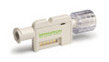
- Sensirion’s STS3x High Accuracy Temperature Sensor
- Its associated breakout board for easy connection
- Solder paste
- Heatgun
- You will also need:
- Arduino Uno
- A lock-type solenoid
- A beefy transistor (TIP120)
- 220R resistor
- Two 10K resistors
- 0.1uF capacitor
- 1N4001 diode
- 12V supply
- And a Wav trigger if you want to rock out to the sounds of the season!
Why?
With springtime approaching, I think it's primative to rely on a groundhog for weather predictions. Why not have an accurate readout that can turn against you and lock you inside for eternity, sort of like Stanley Kubrick's, "2001: A Space Odyssey?" I didn't have much time so I grabbed a tupperware and whatever was in my reach to create what I needed for a smart door. Unfortunately, I didn't add any more than two songs to the sound card so I hope I don't start to go crazy...
The STS3x Temperature Sensor provided a standard I2C communication protocol so I grabbed it and dipped my hands into some DFN soldering while I was at it. By mounting the solenoid on the outside of the door, I assure myself that I really can never get out. Luckily, I included a threshold value that can be lowered to a desired temperature, so you don't have to hibernate with the bears until springtime.

Attempting to mount the enclosure to the "door"
The DFN Soldering
The Sensirion STS3x temperature sensor is a pretty small component, with a footprint of 2.5mm x 2.5mm, so needless to say it needed to be placed on a breakout board for use. To do so, I ordered a standard SMD breakout adapter that provides accurate pin spacing for breadboard use. With no reflow oven and just a single component to mount, I decided to use some solder paste and a standard heatgun to surface mount the device. I should note that this was my first time DFN soldering and with just a few tries I was able to successfully accomplish it.
The solder paste should be spread on each of the land terminals of the breakout board, as well the thermal pad in the center. The pads are very small and the process will probably get a little sloppy, but there's not much else you can do with the tools at hand. Fortunately enough, as you apply heat, the solder naturally becomes smooth and neat and should take to each of the individual terminals. Place the component in the center of the breakout board. Apply heat until you see the solder become molten.

Solder paste, tweezers, breakout board, sensor, finger
When you are finished, grab a multimeter and run a continuity test to ensure that none of the terminals are shorted together. If some are, try heating up the component again and resetting it with a pair of tweezers. When the component is set, wait for it to cool and then flip it over to begin placing the breakout pins on the board.
The bottom of the PCB has large terminal pads. The kit includes 90º breakout pins as well as a PCB spacer that is used to properly space the pins across from one another. Break off the proper number of pins for each side and place the legs through the PCB spacer. Then align the 90º knee against the terminal pads and solder on using a traditional soldering iron and rosin solder. Then, boom, you have yourself a breakout board! Let's get to testing!

The bottom of the pins and the terminal pads

The bottom of the breakout pcb
Getting It Going
There are a few different ways to hook up the STS3X sensor—you can view the datasheet for your specific use. With my configuration, I decided to use "Single Shot Mode" for sake of simplicity. It should be noted that "through appropriate wiring of the ADDR pin, the I2C address can be selected" (datasheet). By connecting my ADDR pin to ground, the address becomes "0x4A". If I had instead decided to connect the pin to a logic high signal, the address would then become "0x4B".
With that in mind, my circuit design was modeled after the example found in the datasheet. You will notice that ALERT and nRESET were left floating. SDA and SCL are plugged into the Arduino Uno's A4 and A5 pins, which can be used to communicate over I2C to the sensor. To do so, we will need to include the Arduino Wire library in our sketch, which can be found below.
When you are confident that everything is wired properly, try running a simple "I2C Scanner" sketch, which will detect any connected I2C devices and display their address. If the address the serial monitor reads matches your sensor's, you have wired it successfully!

My temperature sensor circuit
The solenoid circuit is pretty straightforward and, if you have been keeping up with this series, you can do this with your eyes closed (please don't!). Previously, we have used a relay circuit to control high-current loads—but, with the right transistor, we can do away with the relay. My solenoid here draws an average 500mA current. By using the TIP120 transistor, which can handle a load greater than 500mA, we can safely use the transistor as a switch to connect power to the solenoid.
This circuit will be controlled by a logic high signal sent from digital pin 2 whenever the sensor's temperature value breaks our threshold. As far as the music, I included additional Digital Write statements which send a 5V logic signal to control the Wav Trigger. If you'd like more information on it, check out this great tutorial!
![]()
The solenoid circuit
Getting the Temperature
Specific details for I2C communication can be found within the datasheet and vary for different uses. As stated, I used Single Shot mode and was able to accomplish simple communication using the sketch below (see "void gettemp(){" for specific protocol).
We first begin transmission with the sensor and send two bytes to it. When the sensor receives these bytes, it spits out a value that can be read and then converted by the Arduino.
To do so, we use the 'Wire.requestFrom" and request three bytes from the sensor. The first two bytes indicate temperature and the third is a checksum that is used to verify the validity of the numbers. To convert these numbers into a standard temperature, we must use the equation included in the datasheet. S(t) denotes the raw sensor output for temperature (datasheet).

The equation
Now, open your Serial Monitor and you should see accurate temperature readings! In the first part of the loop, I included a simple If/Else statement to control the solenoid from the sensor's readings. If you would like to change the temperature threshold, simply adjust the number within that statement!
You should now have the components ready to make your own smart door! Find the nearest door in sight and attach it all! Don't forget to include a killswitch so you don't get locked inside for good!
Give this project a try for yourself! Get the BOM.
Other MIT-i Innovations:
- The Cat-Apult! (an Arduino-controlled servo for makers)
- The Launchpad-Based Laser Tripwire Alarm! (a Launchpad security system)
- The Arduino UNIVERSAL Remote Control! (an IR receiver for your entire house)
- The Crop Duster Buster! (a clap-controlled odor-management system)
- The Traffic Light Controller! (an Arduino delay statement lesson)
- The Dancing Ghostbusters Toaster! (a lesson on solenoids and inductive loads)
- The Raspberry Pi Object Detection Cat Toy! (a lesson on the RPi GPIO)
- The Zambroombi! (an object-avoidance robot)
- The Holiday Season Analog Alarm! (a gift-defending system)
- The IoT Beaglebone Beagle Treat Dispenser-Feeder! (a poor excuse for automation)
Related Content