 Facebook
 Google
 GitHub
 Linkedin
The Quark D2000 Development Board: Moving Beyond “Hello World”
Start to get acquainted with the new D2000 microcontroller development board by exploring the GPIO and PWM.
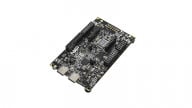
In part one of this series, we introduced the new Quark D2000 Microcontroller development board and reviewed some of its many features. In this part, we will get down to programming some of those features.

The Quark processor
Prerequisites
Please read part one of this series for background information on the Quark D2000.
It is assumed that you have installed the D2000 board software, including the Intel System Studio and have successfully performed an update of the target ROM. Additionally, it is assumed that you have set up a terminal using a USB/serial board and cable and that you have enough familiarity with the Eclipse software to compile and run the “Hello World” example that is included in the software suite.
I was pleasantly surprised by how smoothly all of these steps went when setting up my own board. In fact, except for a simple Windows driver problem, which was remedied by explicitly installing the driver, everything else went without a hitch. I believe that this is due in large part to some very good documentation on how to set up the board provided by Intel, including a step-by-step movie.
Be sure to become familiar with as much of the reference and support resources that you can gather. To get you started, check out these links:
Included Software
All of the example code is included for download at the end of the article. Each example appears as an ASCII text file and is meant to be cut and pasted into an existing template, such as the one for “Hello World” which is included with the software suite.
GPIO
The D2000 has a total of 25 GPIO and each can be independently configured. All digital IO are 3.3v tolerant; applying voltages above 3.3v to an IO pin can damage the chip.
Many of these GPIO serve multiple purposes as described in the Pin Connectivity (PDF) documentation. That is, the 25 GPIO can be configured to serve different functions by setting the pin to one of four user modes [3:0]. By default, after a power-on-reset or a cold reset, all GPIO are in user mode 0 and the example GPIO programs assume that the board is in that mode.
To work with the GPIO, we need to become familiar with the qm_gpio_port_config_t structure that is defined in qm_gpio.h.
Examination of the structure shows the seven members below. The first member is used to set the data direction register. The remaining six members are used in conjunction with interrupts that can be generated through the GPIO:
- uint32_t direction
- uint32_t int_en
- uint32_t int_type
- uint32_t int_polarity
- uint32_t int_debounce
- uint32_t int_bothedge
- void (*callback)(uint32_t int_status)
To configure the GPIO, we first establish an instance of the structure in our code. Next, we configure the data direction register for the specific bit of interest (“0” for input and “1” for output). Subsequently, we can read or write the bit through specific functions.
Inputs
The board includes a user-defined pushbutton, pictured below, that can be used in an example program to demonstrate reading an input bit.

The onboard user button
Referring to the board schematic (PDF), you can see (jump to design sheet 7) that there is a pull-up resistor (562K) from Vdd to the digital IO port 5 and to one side of the switch. The other side of the switch is connected to ground.
When not pressed, the port bit should read “high” and when pressed it should read as “low”.
It can be confusing to determine the relationship between the Quark port bit pins, the schematic labels, the board headers, and the programming code reference. You can find useful tables in the hardware manual (PDF), the pin connectivity manual, and, of course, the board schematic is helpful. For example, from the schematic, you can see that digital IO5 is also referred to as F2. In the tables in the hardware manual, you can see that digital IO 5 (DIO_5) is labelled as GPIO_2 in user mode 0. Our code will need that information.
The simple example program (D2000_Button.txt) assumes that you are in the default user mode 0 and will read the state of the switch and print out the result to the terminal.
Here are key points to the program:
- “Button” is defined as having a value of 2 since we know that the button connects to GPIO2.
- A structure of type qm_gpio_port_config_t is declared as DDRcfg.
- The bit associated with GPIO_2 (i.e., bit 2) is cleared in the structure direction variable with the statement “DDRcfg.direction=0<<2;” to configure the bit as an input.
- With the structure set, we call qm_gpio_set_config(QM_GPIO_0,&DDRcfg) and pass two arguments, QM_GPIO_0, which is defined as a value of 0 (the board has only one set of GPIOs), and the address of our structure, “&DDRcfg”.
- With GPIO_2 configured as we want, we can now read the state of the bit using “qm_gpio_read_pin(QM_GPIO_0,BUTTON);” which will return a boolean value for the input bit.
The rest of the program will simply read and print out the state of the button and changes to the state.

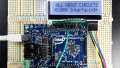
Screen capture of the output of the button program
Outputs
Configuring the GPIO for output follows analogous steps. In the next example, we will blink an LED as a demonstration.
The board contains a user LED and, consulting the schematic, we can see that this LED has a current-limiting resistor and is switched by a MOSFET whose gate is connected to either DIO 09 (F24) or DIO 13 (F16) depending upon the position of a jumper.
That jumper is labelled as J5 and In the “USR” position, DIO 09 will control the LED and that is the position we will use for the example program (D2000_Blink.txt) which simply blinks the LED at .05 Hz.

Jumper 5 in the correct position to route DIO 09 to the onboard LED
The steps in this code are similar to the D2000_Button example except that we define LED as 24 (GPIO 24) and then we set the corresponding bit in the DDR to a “1” using the statement, “cfg.direction=1<<24;”. Thereafter, we can use “qm_gpio_set_pin(QM_GPIO_0, LED);” to turn the LED on and “qm_gpio_clear_pin(QM_GPIO_0, LED);” to turn the LED off.
We use the function “clk_sys_udelay(1000000UL);” which is defined in qm_scss.h, to delay one second. The argument in the function determines the number of microseconds to delay (not including overhead) and depends on the system clock speed, which is normally 32 MHz for the board.
Make Some Sound
In the next example (D2000_Beep.txt), we will use an output port to cycle a 5v buzzer. That is, we will turn it on for one second and off for one second, five times.
The buzzer I used was an old muRata PKB9-3A0 and it is likely obsolete, but most any 5v piezo buzzer that contains internal circuitry will work.
We can use an external 5v supply to power the buzzer but remember that the GPIO on the D2000 is 3.3v only.
One way to accomplish this is to use GPIO 5 (DIO4) to drive the LED portion of a 4N25 optoisolator through a 330-ohm resistor. Do not reduce the value of the resistor as the port bit can provide only 12 mA (16 mA in high drive mode). In my testing, a 1K resistor also worked.
The NPN transistor on the other side of the optoisolator will switch current through the buzzer as shown in the circuit's labeled schematic:

Schematic for the optoisolator/buzzer interface
The advantage of the optoisolator is that we have isolation between the 5v side from the D2000 3.3v side. In fact, in this example, you do not need to connect the D2000 GND and the external power supply GND.
The buzzer that I used draws less than 20 mA, but you should check the specifications for your device and make sure that the 4N25 transistor collector current is rated above the buzzer's draw.
Make a Tone
The 5v buzzer used above has internal driving circuitry that provides the oscillator for the piezo element. That circuitry makes it easy to operate but restricts the sound to a set frequency. In this next example, we will use a magnetic transducer (DBX05) to produce a tone at a programmable frequency.
Specifications for the transducer I used are available here (PDF) and include the frequency response (jump to page 13). This is a typical and inexpensive noise maker that accepts operating voltages from 3 to 8 V.
However, we can’t ask the output port to source the 40mA that the device can pull, so we enlist the help of a 2N4401 NPN transistor. The simple circuit is shown below (with the identification of the few parts used) and the associated program, D2000_Tone, will “play” a 2400 Hz tone at variable durations.

Schematic for the magnetic transducer interface
We want to operate the transducer at 2400 Hz, which means that the period is ~416.7 microseconds.
For our square wave, the output will be high for half of the period and low for the other half. We can implement this by simply setting the bit high and delaying for ~208 microseconds and then bringing it low for ~208 microseconds. As long as we repeat the sequence, we will be generating the tone.
We also, however, need to be able to control the duration of the tone. One solution is to make use of an internal timer in the operating system. If you look at the file, qm_scss.c, which is included in the software suite, you can see the code for the function clk_sys_udelay() which we previously used to perform a microsecond delay.
Note that the function calls another function, _rdtsc(), which returns an unsigned long long (presumably 64 bits—see here) containing the timer value. That is the function that we will use to take a snapshot of the internal timer which uses 32 ticks per microsecond at the normal 32 MHz clock speed. If we then add our duration to that value, we can perform a while loop test to determine if our duration has elapsed. Within the while loop, we will toggle the output bit to achieve the desired frequency.
If you look at the included program, D2000_Tone, you can see the function play(duration), which will play the 2400 Hz tone for the duration given in the argument (as 1/32 microsecond counts). The main program simply outputs some text to the terminal and plays five such tones of one-second duration separated by 0.5 seconds, and then five tone bursts of 0.25 second duration, also separated by 0.5 seconds.
You could actually build on this short piece of code such that the frequency, as well as the duration, can be sent as arguments to the play function and develop some musical note capability.
Pulse Width Modulation (PWM)
The D2000 has two outputs capable of PWM and that’s the good news. The bad news is that you can only use one of them, PWM1. At the time of this writing, using PWM0 will cause trouble for some JTAG pins and prevent flashing and debugging of the board. This is a known issue and, hopefully, there will eventually be a workaround.
The final example (D2000_PWM) will, therefore, use PWM1.
The output bit for PWM1 is F24, DIO 09. That bit is connected to an onboard LED (depending upon the position of J5)— we used that LED in the D2000_Blink example earlier. Because it is so convenient, we will use the same LED for the PWM example.
To demonstrate the PWM, we will increase and decrease the intensity of the LED by varying the duty cycle. The effect should be observed as a kind of softened blink and should be easily distinguishable from the D2000_Blink program.
For this example, we first declare two arrays: one for the “on” periods and one for the “off” periods. These values will determine the number of cycles the pin is driven high and low, respectively. By making these values add to the same number, we can easily configure the duty cycle in terms of a percentage. We then declare an instance of the configuration structure, qm_pwm_config_t. If you look into the header file, qm_pwm.h, you can see the definitions of this structure and we use the elements as follows:
- lo_count — This is initially set to the first element of our “off” period.
- hi_count — This is initially set to the first element of our “on” period.
- mask_interrupt — This is set to “true” since we are not using the interrupt capability.
- mode-set to QM_PWM_MODE_PWM — This is defined as 10. This defines PWM mode in contrast to one of two timer modes available.
- (*callback) — We don’t use this since we are not using an interrupt, but it would reference our interrupt service routine, if we did.
Next, we enable clocking for the peripheral device with the statement: “clk_periph_enable(CLK_PERIPH_PWM_REGISTER | CLK_PERIPH_CLK);”. The bit values in the argument are defined in the header file, qm_scss.h. Then we configure the PWM by calling the function qm_pwm_set_config() using arguments defining which PWM and pointing to our configuration structure.
Before we start, we have to configure the pin for function 2 using the statement, “qm_pmux_select(QM_PWM_CH_1_PIN, QM_PWM_CH_1_FN_PWM);” Remember that the pin we are using is muxed and we want to set the function to user mode 2, which is PWM. The arguments are defined in the program and they are simply the port bit number (24), and the user mode (2), respectively.
Finally, we can start the PWM with the statement “qm_pwm_start(QM_PWM_0, QM_PWM_ID_1);”. The arguments here were also used when we set the configuration, and they can be a little confusing. I think of the first argument as the “bank” of PWM and the D2000 board only has one, so that argument is “0”. The second argument determines which PWM within the bank, and that is PWM1. Thus, the argument values are 0 and 1, respectively.
At this point, the pin is exhibiting the duty cycle that we set it to, but we want to dynamically change that duty cycle in order to increase and decrease the brightness of the LED. This is accomplished in the for-next loops that cycle through the “on” and “off” period arrays, first increasing and then decreasing the duty cycle. We do this every 45 milliseconds.
I chose nine different duty cycles and the values, in my view, produce a pleasing increase and decrease. After we loop through the duty cycles 30 times, the program ends.
Closing Thoughts
This article has examined programming the GPIO and PWM features of the Quark D2000 Development board and is intended to provide a user-friendly introduction to exploring those features.
The included examples, however, only scratch the surface of the many capabilities of the board, which also include ADC, I2C, SPI, comparators, and more.
In general, I remain enthusiastic about the D2000 as a powerful but very low-priced controller with an included software suite.
Code
Download the code examples here:
Give this project a try for yourself! Get the BOM.


Thanks fpr the informative article.
I just compiled the D2000_PWM1 example with Intel SSMI Update 2 and encountered an error in main.c line 3.
#include “qm_scss.h” file is not found
I replaced the line with
#include “clk.h”
And it compiles and executes just fine.
I don;t have SSMI update 1 so cannot say if that is the issue