 Facebook
 Google
 GitHub
 Linkedin
Classical R-C Oscillators: The Bridged-T Network and the Wien Oscillator Network
Learn more about these two classic oscillator network topologies, including their simulations.
If you’re looking to design a tunable low-distortion sinusoidal oscillator covering audio and low radio frequencies, odds are high that you would first consider some of the classical R-C oscillators found in textbooks for decades, such as those with a feedback loop around the Wien or Bridged-T networks.
These R-C networks provide a phase shift that varies with frequency so that at one particular frequency the total phase shift around a feedback loop is zero. The gain around the active feedback loop surrounding the network overcomes the attenuation of the passive R-C network, and the oscillation settles at the zero phase shift frequency.
In this article, we'll take a look at these classic networks—and discuss some of their limitations.
The Classical Oscillator Networks
Here, we'll review some basic schematics of oscillators built around the classic Wien and Bridged-T networks using, for example, dual ganged variable resistors for tuning.
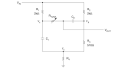
Figures 1 and 2 show an active feedback loop with the incandescent bulb amplitude stabilization introduced by L.A. Meacham in 1938 and used in the HP 201A:
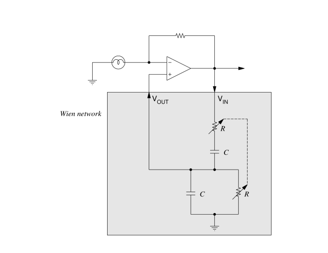
Figure 1. Basic schematic of an oscillator built around the classic Wien network
For the Bridged-T network, α is some design factor greater than one, and typically two to four:
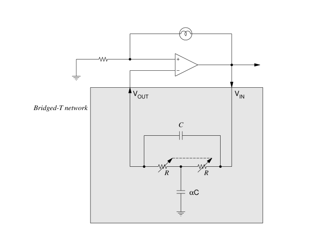
Figure 2. Basic schematic of an oscillator built around the classic Bridged-T network
With a little circuit theory, we can derive that the zero phase shift frequencies for the Wien and Bridged- T networks are the following, respectively:
- Wien network: $$f_{osc} =\frac {1}{2\pi{RC}}$$
- Bridged-T network: $$f_{osc} =\frac{1}{2\pi\sqrt{\alpha}RC}$$
The attenuation through the networks at these resonant frequencies are factors of 3 and $$\frac{2+\alpha}{2}$$, respectively.
The Wein network realizes a bandpass filter and the Bridged-T network a band-reject filter, and this difference accounts for the difference in feedback polarity and bulb placement for the amplitude to stabilize.
Focusing on the classical Wien and Bridged-T networks in the shaded boxes in these schematics, SPICE simulations of the magnitude and phase of their sinusoidal transfer function $$\frac{V_{OUT}}{V_{IN}}$$ as a function of frequency are plotted in Figures 3 and 4.
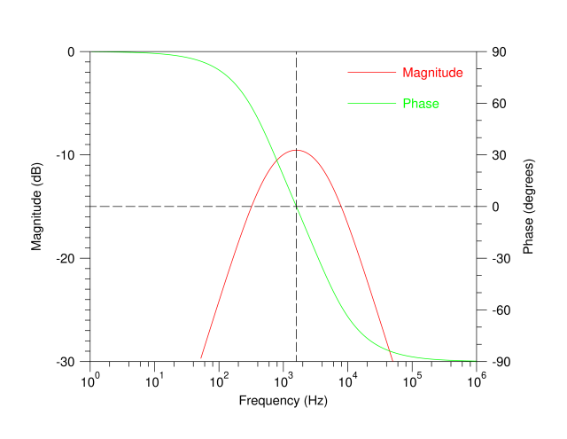
Figure 3. Simulation results for the Wien network with R=10kΩ, C=10nF
The dashed lines in these plots mark the oscillation frequency where the green phase lines pass through zero degrees. The points where the dashed lines hit the red magnitude lines mark the attenuation that the feedback gain must overcome. An attenuation factor of 3 for the Wien network reads as a magnitude of -9.5 dB in Figure 3.
The Bridged-T network is simulated with a typical value of $$\alpha = 4$$. With these values, the attenuation at resonance is $$\frac{2+\alpha}{2} = 3$$ just as in the Wien network.
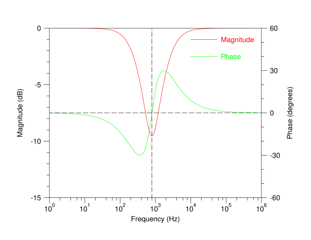
Figure 4. Simulation results for the Bridged-T network with R=10kΩ, C=10nF, α=4
The Trouble with R-C Oscillator Circuits
But tuning these classical networks over a wide frequency range is difficult in practice.
In all of these circuits, at least two resistors or two capacitors must be varied, and the variations must track very closely to keep the network attenuation constant with frequency.
For example, in the legendary Model 201A oscillator instrument based on the Wien network, Hewlett-Packard used a large multiple-section ganged variable capacitor to keep this tracking close. Dual-ganged variable resistors are smaller, but quite expensive when built to keep in close track. Unless the network attenuation is kept constant over frequency, the oscillator output amplitude will vary over its tuning range, an undesirable property for a test instrument.
A Possible Solution: The Sulzer Network
There is one option that many engineers don't realize they have: the Sulzer oscillator network.
In my article on the subject, we'll look at the complex network Sulzer created and compare it to the results we've obtained here from the Wien and Bridged-T networks.


There is a very good design in the old National Semiconductor Linear Circuits Handbook; “An Easily Tuned Sine Wave Oscillator”. One company I worked with used that design to replace its older phase shift oscillator design that used germanium transistors. The NS design was very stable over an industrial temperature range. I believe we used metal film resistors and polystyrene capacitors.
Worth mentioning that the Wien bridge.oscillator with incandescent lamp stabilisation was the subject of Bill Hewlett thesis and made the first product of the HP company: the HP200