Facebook
 Google
 GitHub
 Linkedin
Digi-Key’s Scheme-It: Schematics and System Diagrams
This article will provide a brief overview of the capabilities and advantages of using Scheme-It when starting a new project, especially when working with a group.
If you've ever lacked the tools to easily start your next design concept and share it with a team, Digi-Key's Scheme-It could be the answer.
The Scheme-It Interface
If you've spent any time recently looking around the Digi-Key website, you may have already found Scheme-It in the "EDA & Design Tools" page of their resources section. It's easy enough to jump into—you don't even need to install anything locally since you can use an in-browser app.
When you open this app, it brings you to a dialog box with the options "Try It Now" (a trial version which will give you no save capability) and "Register/Login".
Once you're in, you'll see a nice, clean interface with some pretty self-explanatory buttons along the top.
The Export button is of particular note, as it lets you take your creations and output them in image or PDF format, as well as a BOM for Digi-Key's companion tool, PCBWeb (we'll touch on this again a little later).
Share lets you grab either a link to provide to others, or an embeddable window—like the one above—to put onto a webpage (but note that you'll first have to make the design public).
Another option along the top row to keep in mind is the Insert menu, which lets you add text blocks, images, and links to better describe what you're making.
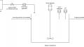
For convenience, I've included an embedded window for a sample project below (again, clicking on the project name in the top left will open the project in the Scheme-It app and give you a better view). This embedded Scheme-It window shows a partially-finished draft for another project being written about on the AAC website (C-BISCUIT), in which you can see some of the schematic design features being put to use:
In order to get the full view of the Scheme-It tool, you'll have to click on the project name, or some of the features I mention will seem mysteriously absent. The design in question is for an I/O board based off of the STM32 NUCLEO-F303K8, and you can see that I've put a few details in the design notes (to view these, you can click on the three-bar symbol in the top-right corner and go to "Notes"). There are three sheets being employed for system components, and this draft I've shared with you lacks a lot of final touches, but it also shows the power of the tool.
All of the IC part symbols shown were manually created using the Custom Symbols drop-down on the left:
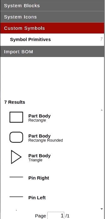
Placing symbols (not just the custom ones) is pretty straightforward. Best of all, it lets you assign part data straight from the Digi-Key inventory.
Try clicking on any part in the diagram—you should see a menu appear on the right side of the screen with some designator fields to fill in, along with a Catalog Assign button. This button lets you search the Digi-Key website and add part numbers, manufacturer names, etc. to the symbol you've placed, which will then automatically be ported to the BOM page (more on that in a bit). It's easy with this feature to quickly put together system blocks and an entire parts list for your project, especially if you are making something with many identical sections.
Your standard copy/paste/delete functions are readily available with the standard keyboard shortcuts, as are the ability to zoom (I for In, O for Out, F for Zoom to Fit), flip (V for Vertical, H for Horizontal), and rotate (R). You can also use CTRL+E to edit the properties of a selected part, and even press A when selecting one to go immediately to the Catalog Assign section.
A Note About Connections
One of the interesting aspects of Scheme-It which sets it apart from many other schematic editors is the way you connect parts together. Instead of having to click or press a "Draw Wire" or "Add Wire" button before starting, you just click the part's pin, and then you can direct it where it needs to go, using additional clicks to make 90-degree turns where necessary. This extends even to higher-level symbols available in the symbol library, such as SD cards, wind turbines, and UML symbols—you'll just have to click the yellow arrow in the center of the symbol to create a wire from it to another part.

Considering the sheer number and variety of symbol types available, I think this makes Scheme-It a great tool for brainstorming. It also even makes it useful for educational purposes because of its potential for creating customizable schematics that can be shared online with others. Not only that, but you can work over a range of detail. You can choose whether to go with the flow chart and UML tools (numerous colour-coded shapes in the System Blocks section representing, for example, power sources, memory, and logic) or the schematic part symbols (seen above) to get the job done.
The Bill of Materials and Exporting to PCBWeb
One of the downsides to using Scheme-It is that you can't create netlists for export into the companion software, PCBWeb. This isn't a huge loss, though! Since Scheme-It includes all of the features you need to start laying out concepts and conveying ideas, the existing BOM functionality is an excellent bridge between simple drawings and a full-blown hardware design.
As another example of what you can do with the Scheme-It library, take a look at the simple design I've embedded below. This is a higher-level overview of a concept using the array of symbols available in the Scheme-It library. It took almost no time at all to throw this together, and system diagrams like this can go a long way to getting everyone on the same page in a group project.
If you take a look at the BOM page, you'll see that only three of these parts—the Wandboard Quad, the Wandboard Antenna, and the Wandboard enclosure (the pink block on the bottom left)—are included. If you've only got a partial BOM available for a project because you're custom designing a subsystem or getting a part elsewhere (like in this example), that's not a problem for the BOM tool. Try clicking on Order and see what I mean. After telling it how many copies of the assembly you intend on making, you'll be taken to a Digi-Key order page with all of the parts from your list that they could find in the catalog.
On the other hand, if your current design consists largely of through-hole or SMD parts that you want to put onto a board for manufacture, you're covered there as well. The Export button on the main menu includes an option to generate a BOM for PCBWeb, which the designers of Scheme-It have also conveniently provided a link to along the top of the screen.
Once you've imported your list of parts to PCBWeb, you can then give them fully-customized schematic symbols as well as footprints before putting together a PCB to suit your needs.
Last Words
I hope this article has given you a sufficient overview of Scheme-It, and convinced you to consider it in the future (I know I'm going to be using it pretty often). Happy hacking and/or designing!