 Facebook
 Google
 GitHub
 Linkedin
How to Design a Bluetooth Low Energy Circuit with Sensor Technology
Tutorial on designing a Bluetooth Low Energy (BLE) circuit with the ability to measure 9-axis motion, humidity, and temperature.
Tutorial on designing a Bluetooth Low Energy (aka Bluetooth Smart) circuit with the ability to measure 9-axis motion, humidity, and temperature.
In this article, I'm going to cover the circuit design for a Bluetooth Low Energy (BLE) product that features an accelerometer, magnetometer, and gyroscope, as well as sensors for measuring humidity and temperature.
One of many possible applications for this design would be a small device to monitor the shipping conditions of critical items during transit. After shipment, the data from the journey can be downloaded over the BLE link to be analyzed. Did employees mishandle the item? Maybe play football with it? This device can tell you.
Also, keep in mind that this design is highly extensible—it would not be difficult to incorporate other types of sensors.
NOTE: Throughout this article I will be using the following terms interchangeably: Bluetooth Low Energy, Bluetooth LE, BLE, and Bluetooth Smart. They all mean the same thing.
Bluetooth Low Energy / Bluetooth Smart
Designing a new Bluetooth product, or any wireless product, can be somewhat challenging for the inexperienced. This is primarily due to the complexity of the PCB layout for the RF (radio frequency) section. Fortunately, in BLE microchips, most of the RF circuitry is internal, so you don't need to worry about much more than the layout for the antenna.
Bluetooth Low Energy is a very popular open wireless standard for short-range communication. The range is typically about 50 feet, although this can be significantly increased with the use of a range extender circuit that either increases the receiver sensitivity, increases the transmission power, or both.
As the name implies, Bluetooth LE is a low-energy version of "classic" Bluetooth and thus is more appropriate for ultra-small devices powered by a single watch battery. BLE is the primary wireless technology for Internet of Things (IoT) products.

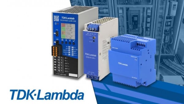
Example of a Bluetooth LE module. Image courtesy of Digi-Key.
BLE is designed for devices that require only intermittent transmission of relatively small packets of data, rather than, for example, streaming audio. Most modern smartphones and tablets support Bluetooth Low Energy. It is supported by Android versions 4.3+ and by Apple iOS versions 4s+.
Bluetooth Smart devices communicate using radio frequencies in the 2.4 GHz industrial, scientific, and medical (ISM) band. BLE-enabled devices can support a wide array of applications and products, from remote controls and smart toys to short-range monitoring with wireless sensors. BLE devices are covered by version 4.0+ of the Bluetooth specification.
Integrating BLE into a system can be accomplished by selecting a microcontroller that offers BLE functionality or by using a BLE module. The use of a module will simplify the design and drastically reduce certification costs—but it will also increase the production cost. However, in most cases, a non-module BLE solution only makes economic sense once manufacturing volumes exceed about 500k units.
One such BLE microcontroller is a member of the Cypress CYBL10X6X family based on an ARM Cortex-M0 processor. One nice thing about the Cypress line of BLE microcontrollers is that they also offer BLE modules based on these microcontrollers. This can make the transition from a module solution to a more-customized solution a smoother process.
Schematic

The project's schematic. Click to enlarge.
BOM
| Quantity | Value | Name and Datasheet | RefDes | Description |
| 1 | CYBL10161-56LQXI | U1 | Cypress BLE microcontroller | |
| 1 | MPU-9250 | U2 | InvenSense 9-axis motion sensor | |
| 1 | HDC1080 | U3 | Texas Instruments humidity/temperature sensor | |
| 1 | 24MHz | NX2520SA-24.000000MHZ | X1 | Microcontroller crystal |
| 1 | 32.768kHz | ABS06-32.768KHZ-9-T | X2 | Microcontroller crystal |
| 1 | W3008 | ANT | Bluetooth chip antenna | |
| 10 | 1μF | GRM188R61C105KA93D | C1-C10 | Ceramic capacitor |
| 11 | 0.1μF | CC0603KRX7R7BB104 | C11-C21 | Ceramic capacitor |
| 1 | 36pF | GRM1555C1H360JA01D | C22 | Ceramic capacitor |
| 1 | 18pF | CBR04C180F5GAC | C23 | Ceramic capacitor |
| 1 | 100pF | GRM1555C1H101JA01D | C24 | Ceramic capacitor |
| 1 | 10nF | CC0603KRX7R9BB103 | C25 | Ceramic capacitor |
| 1 | 1.2pF | GRM1555C1H1R2CA01D | Cpi1 | Ceramic capacitor |
| 1 | 1.5pF | GJM1555C1H1R5BB01D | Cpi2 | Ceramic capacitor |
| 1 | AO7401 | MP1 | P-channel MOSFET | |
| 3 | BLM18AG102SN1D | FB1, FB2, FB3 | Ferrite bead | |
| 1 | 6.8nH | L-07C6N8JV6T | Lpi3 | Inductor |
| 3 | 10k | RC0603JR-0710KL | R1, R2, R3 | Resistor |
| 1 | 22232051 | J1 | Programming connector |
Components Discussion
The main components are the Bluetooth Low Energy microcontroller (U1, CYBL10161), the motion sensor (U2, MPU9250), and the humidity sensor (U3, HDC1080). The system is powered by a 3.7 V lithium polymer battery.
There are two crystal oscillators used by the Cypress CYBL10X6X: the 24MHz external crystal oscillator (ECO) and the 32.768kHz watch crystal oscillator (WCO). The Cypress microcontroller includes internal, tunable load capacitors for the 24MHz crystal. Thus, in contrast to crystal-oscillator circuits for most microcontrollers, the 24MHz crystal in this design requires no external load capacitors.
The Cypress microcontroller is programmed via a Serial Wire Debug (SWD) interface on connector J1.
All power pins on each IC have bypass capacitors and use the recommended values given in the datasheets. Ferrite beads FB1, FB2, and FB3 provide some noise isolation between the digital, analog, and RF sections of U1.
Most components in a design need a clean, stable voltage. Power supply capacitors should be placed near the power supply pins on each IC to stabilize and filter the power. These decoupling capacitors provide a local storage reservoir and lower the effective impedance on the power supply traces as seen by the IC power pins.
Usually, designers will place a 1.0μF (or larger) capacitor in parallel with a 0.1μF or 0.01μF capacitor in order to achieve low impedance across a wide band of frequencies. Capacitors of X7R dielectric are sufficient for use as power supply bypass capacitors.
For highly sensitive components, such as this RF microcontroller, a ferrite bead should also be included. This creates a low-pass filter that suppresses high-frequency power supply noise generated by other parts of the system. This design uses three ferrite beads (FB1, FB2, and FB3), one for each VDD supply (digital, analog, and radio) required by the microcontroller.
Humidity / Temperature Sensor
U3 is a digital humidity sensor (the HDC1080 from Texas Instruments) and is connected to the controller through an I2C serial interface. The device can measure relative humidity with up to 14 bits of resolution with accuracy better than ±4% over a temperature range of -20°C to 70°C.

Image courtesy of ClosedCube.
The HDC1080 can also measure temperature over the range of -40°C to +125°C with accuracy better than 0.6°C. In addition to measuring temperature and humidity, the HDC1080 includes a battery monitoring circuit which will set a status bit if the battery is below 2.8 V. The supply voltage range is 2.7 to 5.5 V.
I2C is an addressable serial bus, so each I2C slave device in the system must have a unique address. For the HDC1080, the 7-bit address is pre-set to b1000000. The MPU-9250 motion sensor allows you to choose between two addresses: b1101000 or b1101001. The least significant bit is set to one or zero by tying the AD0 pin high or low. Note that pull-up resistors (R1 and R2) are required for each of the two I2C lines.
The device manufacturer provides recommendations concerning the placement of the sensor on the PCB. For example, the HDC1080 should not be placed close to any heat-generating components.
Power and ground planes in the PCB should not run under the device, because they could provide an unwanted thermal path to the sensor. In fact, slots should generally be placed around the device to separate it as much as possible from the rest of the board.
9-Axis Motion Sensor
U2 is a motion sensor (MPU-9250 from InvenSense) that includes a 3-axis accelerometer, a 3-axis gyroscope, and a 3-axis magnetometer (compass).

Image courtesy of InvenSense.
This type of sensor detects movement of the device itself and is not to be confused with ultrasonic or infrared sensors that detect motion of a nearby object (such as those used in motion-activated lights).
The MPU-9250 includes nine analog-to-digital converters, each having 16 bits of resolution. The MPU-9250 interfaces to the microcontroller via the I2C bus.
The Antenna
When not using a pre-certified BLE module with a built-in antenna, one of the most critical aspects of the design will be the antenna and the transmission line between the antenna and the transceiver.
There are two choices for the BLE antenna: a chip antenna or a PCB-trace antenna. A chip antenna has the advantages of smaller size and simplified tuning. A trace antenna is designed into the PCB itself. The main advantage of a trace antenna is the reduced unit cost. In fact, because the antenna is just a trace on the PCB, the antenna is essentially free.
However, chip antennas are rather cheap, so in most cases a chip antenna is a better choice—at least initially.
This design uses a chip antenna from Pulse Electronics. Once your product achieves large production volumes, you may want to replace the chip antenna with a PCB-trace antenna in order to reduce your unit cost and improve the profit margin.
PCB trace antennas tend to be more problematic to tune, however, and many times they require several PCB revisions in order to optimize tuning. Modifications to the PCB will also have a more pronounced impact on a trace antenna's tuning versus that of a chip antenna.
Antennas always need to be tuned for peak performance. Tuning is a complex process that requires a special type of testing chamber that shields and absorbs all types of radio waves. So antenna tuning is usually best outsourced to vendors specializing in tuning. In many cases, though, the antenna manufacturer (Johanson Technology, Pulse Electronics, and Taoglas, for example) will offer tuning services for new designs incorporating one of their antennas.
An antenna will normally require the use of a pi-network for tuning the antenna (i.e., altering the impedance of the antenna so that it more closely matches the impedance of the transceiver). The capacitor and inductor values used in the pi-network are adjusted so as to maximize the power transfer between the antenna and the RF transceiver.
If optimizing the operating range isn’t extremely critical for your product, then a chip antenna doesn’t necessarily need to be tuned for BLE, at least for early testing.
Critical aspects of the antenna layout must be adhered to in order for the antenna to operate correctly. The designer must pay careful attention to recommendations in datasheets and application notes.
You can determine the PCB transmission line dimensions for achieving proper impedance matching by using a special calculator such as the free tool AppCad from Avago.
Certifications
Each country has its own regulations concerning the emission of radio frequencies, and every BLE system must be in compliance. In the United States, the FCC regulates emissions in the 2.4 GHz ISM band, and if the product is sold commercially, FCC certification is required.
FCC certification usually costs a minimum of about $10,000 for a custom-chip (i.e., non-module) solution (which is classified as an "intentional radiator"), versus only about $1,000 for a solution using a BLE module (classified as a "non-intentional radiator").
Both "classic" Bluetooth and Bluetooth Low Energy require you to pay an $8,000 licensing fee. This is true whether you use a pre-certified module or a chip solution.
The designer of a BLE system should be aware that significant testing expense, certification cost, and design effort can be avoided by using a pre-certified BLE module.
If you would like to learn more about developing a new electronic product, check out my Ultimate Guide - How to Develop a New Electronic Product.
Related Content


The design manifested for the bluetooth low energy circuit is the future, which can pave way too many gadgets without emitting any harmful rays through it. As these gadgets can be helpful for the creation of a new technology worldwide.
I would like to build a module like this that detects movement, and out of range temperature and humidity conditions. Upon detection of these conditions, sends out notification text via a WiFi router. The project shown is ideal because of its small size and battery operation, but I don’t believe bluetooth is the correct conduit for talking to a WiFi router. While I understand that this site is focused on DIY, I would also be interested in info on existing inexpensive products that might fit the bill to understand the design time/cost risk vs purchasing an existing product. Thanks…Steve